 The Academy
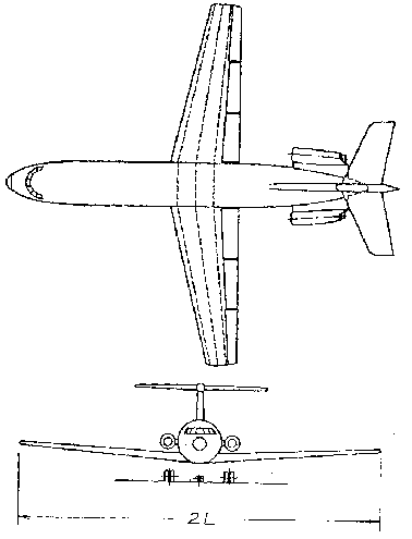
This project involves the design and analysis of an aircraft wing from a typical light weight corporate jet as shown in Figure 1.
The project will involve the selection of particular wing properties subject to satisfying certain design criteria, and to then use these properties to develop a Working Model Simulation to determine the natural frequency of wing oscillations. The design requirements are listed below:
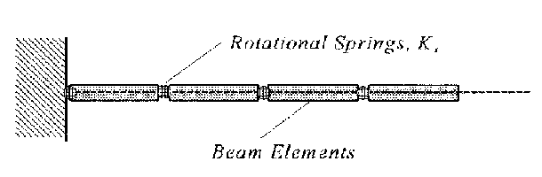
Although each section is still a rigid body, the rotational springs allow the beam to flex as the actual wing does. In this fashion, a continuous vibration problem is modeled as multi-degree of freedom lumped-mass problem. An important parameter in developing an accurate model is the choice for the rotational spring constants. By comparing several cases through matching deflections of the joints of the discretized beam with those predicted by Euler beam theory, previous research has determined that the spring constants should be selected using the criteria
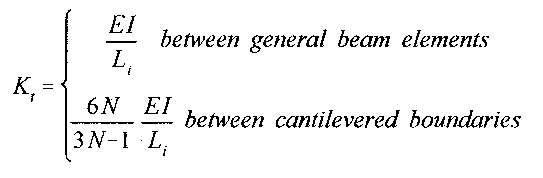
where N is the number of discretized elements and Li is the beam element length.
Using the above specifications, develop a four and an eight degree-of-freedom Working Model simulation for the free vibrations of your designed wing. In discretizing the wing, use beam elements that are of equal size and properties, and keep the beam height approximately equal to 6in. Specify all chosen parameters used in the models, and plot the vertical displacement of the outermost beam element to determine the natural frequency of each Working Model wing simulation. Finally compare your results with those from the exact solution for the first mode of a continuous beam given in the text, Figure 8.15, page 527. From the table, choose the first root of the frequency equation for the fixed-free case, where the natural frequency is given by