 The Academy

1. INTRODUCTION
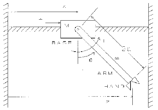
In this project you will design a controller for a gantry robot, and run a software package called Working Model to check the performance of your design visually. Gantry robots have a moving base that supports an arm. Typically, the arm is suspended below the base (See Figure 1). Because of this arrangement, gantry robots are used in applications requiring a larger workspace than is obtainable with a fixed-base robot arm. Most gantry robots are supported by a structure with four legs and have a base that can move in both horizontal directions. The base is driven by a lead screw in each direction. The arm usually has several joints that allow it to position the hand at a desired location with a specified orientation. The simplified planar version in Figure 1 has a base that moves in the x direction only and an arm with two joints - one joint to rotate the arm, and one joint to rotate the hand.
Assumptions. We will assume that the hand's mass is small compared to the arm's mass m, and thus we will neglect the hand's dynamics and kinematics. We will assume also that the time constants of the an-n motor and the base motor/lead screw system are small compared to the time constants of the base and arm. This means that the motors act almost "instantaneously" to produce the force f and the torque T.
Linearization. The model derived in class is nonlinear, but can be linearized if we assume that 0 and its time derivatives are small, so that the following approximations are accurate:

The linearized model is


which has the characteristic equation:

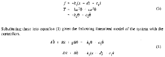
Note that z = x + 2a sin (theta). Let us assume that the application requires that the hand be positioned near some desired position z = d. One way to do this is to keep the an-n near vertical (theta near 0) and the base position x near the desired position d. To achieve this we introduce a controller that commands the arm motor to apply a torque T like that produced by a spring and damper. Similarly, we introduce another controller that commands the base motor to apply a force f like that produced by a spring and damper plus a constant force kld. Of course, the springs and dampers do not exist in the actual system. Their action is reproduced by the controllers, which use sensors to measure theta, x, and their time derivatives. Thus the controllers apply the following force and torque:


If the term B2/AD is small, then the arm dynamics are approximately uncoupled from the base dynamics, and the four roots of the above equation are approximately the roots of

3. CONTROLLER DESIGN
The design problem is to select values for the controller gains k1, c1, k2, and c2 so that the base and arm motion will move the hand to the desired position z = d. Note that as the base accelerates and then decelerates, the arm will tend to oscillate; the ann controller must compensate for this in order to position the hand at z = d.
The specific design requirement for this project is as follows: with the system started from rest at x(O) = O(O) = 0, the hand position z must settle to within 5 % of d after 4 seconds. In addition, the hand must not overshoot the desired position by more than 1 0 % because it will hit a wall (i. e. z < 1. 1 d). Use d = 5 ft and g = 32.2 ft/sec2
Note that this involves the step response of equations (5) with a step input equal to k1d. Note also that a 5% settling time corresponds to 3(tau).
Use the value a = 3.5 feet. For the values of M and m assigned to you, compute values for k1, c1, k2, and c2 to satisfy the above requirement. There are many possible solutions and many ways to obtain a solution. Treat the base a second-order system, and select k, and cl to obtain an appropriate time constant, or overshoot, or peak time, or delay time, or rise time, or some combination of these. Then use a similar approach with the arm subsystem to select k2 and c2
For example, one approach might be to choose k1 and c1 to make the base critically damped with a time constant of 4/3 sec, and choose k2 and c2 to give the arm a delay tirne of 2 sec with an overshoot of 5 %. (Caution: I used a different approach, so I do not know if this approach will work.)
4. CHECKING YOUR DESIGN
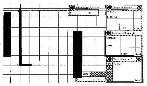
After you calculate values for k1, c1, k2, and c2, you will check your design by running it on Working Model, a software package that graphically simulates mechanical systems.
(Instructor's Note: The following page shows the Working Model screen for this simulation. The gantry robot is in the middle, with two walls, on each side. If the controller is not designed properly, the robot might hit one of the walls. The meters are used to collect data, which is exported to Microsoft Excel for plotting.)
