
Objectives:
Develop and apply a design tool using Working Model to study and the kinematics and
kinetics of internal combustion engines
Instructional Objectives:
To reinforce concepts of rigid body dynamics. Learning Working Model features including
pins, joints, slots, motors and frames of reference.
Background:
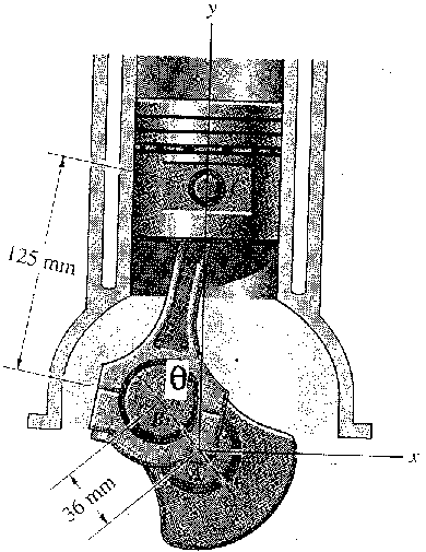
Internal combustion engines provide an excellent example of a mechanical system for analysis
using rigid body dynamics. The engine has three primary moving components: the piston, the
connecting rod, and the crankshaft. The piston experiences translational motion without rotation,
the crankshaft experiences rotation about a fixed axis, and the connecting rod experiences general
plane motion including both translation and rotation. Working Model provides an excellent tool for
visualizing these motions and computing velocity, acceleration and force histories.
Problem Statement:
Consider the following one cylinder, two stroke internal combustion engine.
In this exercise we seek to model the motion of the engine and to determine the dynamic forces induced during operation. As in our dynamics course, we will separate the exercise into two parts: a) rigid body kinematics and b) rigid body kinetics. To help you in setting up the simulation, a copy of a tutorial provided with Working Model is attached.
a) Rigid Body Kinematics
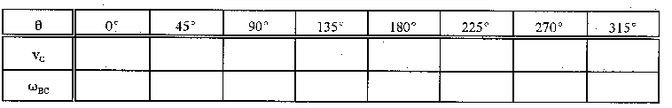
If the crankshaft rotates at an constant angular velocity of 6000 revolutions per minute, calculate (by hand) the velocity of the piston vC and the angular velocity, WBC, of the connecting rod when Õ = 45o. Develop a Working Model simulation of this problem and verify your results. Also determine vC and WBC for the following positions:
b) Rigid Body Kinetics
To model the kinetics of the engine, we apply a force history to the piston. During combustion, the piston moves downward due to the relatively high applied force, F1. As the piston moves upward, it acts to force the exhaust gases out of the cylinder and then to compress the fuel/air mixture. Hence, a relatively small force, F2, is applied to the piston as it moves upward. We will approximate these forces, F1 and F2, to be constant and will take them to be
Resisting the rotation of the crackshaft are various internal friction effects which contribute to a net resisting torque applied to the crackshaft. It has been found that this frictional torque increases with speed according to the equation
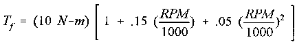
where RPM is the engine speed in revolutions per minute (rpm). An additional torque, T0, is associated with the external load applied to the engine.
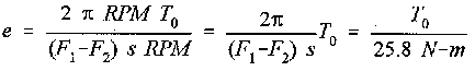
The efficiency of the engine, e, is defined as
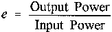
where the input power is due to the forces applied to the piston:

where s is the stroke of the piston (72 mm). The output power is given by

Hence, the efficiency of the engine is given by
In this assignment, you are develop a Working Model simulation to determine:
| Mass (kg) | Mass Moment of Inertia (kg-mm2) | |
| Piston | 0.5 | 150 |
| Connecting Rod | 0.4 | 6,000 |
| Crankshaft | 2.5 | 10,000 |