![]()
![]()

Objectives:
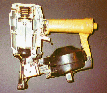
To examine the details of the design of an existing commercially available
pneumatic fastening tool, similar to the one shown in Figure 1, for attaching
roof shingles to plywood. To develop a Working Model simulation of components
of the device including the piston, piston "O" ring seals, a
typical nail, the force acting on a nail during penetration of wood, and
the characteristics of an energy absorbing safety bumper. To exercise this
simulation to determine:
A second objective will be to use the value of the average pressure required to set a nail to investigate the design trade-offs inherent in choosing an accumulator volume (basically the volume of the guns handle and some additional internal spaces) given the availability of a certain level of supply pressure. This will be done graphically using EXCEL and assuming the gas expansion process is isentropic.
Instructional Objectives:
Use the features of Working Model, particularly the polygon tool and
its geometry window, to develop a simulation of two disparate masses (the
piston and the nail) colliding. Understand the role played in this by the
elastic constant (coefficient of restitution). Expand the students ability
to program a complicated force time history into Working Model. Understand
how to incorporate non linear springs in a working model simulation. Experience
the use of results from Working Model to perform other computations required
to carry out an overall design of a complete product.
Background:
The nail gun we will be concerned with in this project is manufactured
by Stanley Bostich which is located in East Greenwich Rhode Island. It
is one of at least eight closely related products in their pneumatic fastener
line of tools for the construction industry. The tool we will study is
a version of their model RN45 Coil Roofing Nailer which is used to attach
asphalt shingling, insulation board, vinyl siding, and fiber cement roofing
and siding.
The galvanized and stainless steel nails used with this nailer range in size from 3/4 of an inch to 1 3/4 inches and come in a coil, closely spaced, and individually welded to two parallel carrying wires. This coil of nails is loaded into a cylindrical magazine and feed into the gun by an air powered ratchet system which operates by bleeding off a small amount of the compressed air used to power the gun and to drive the nail.
Such pneumatic fastener tools are usually powered on site by a small portable air compressor. Our tool would normally operate off of a two horse power compressor. Such a compressor would be equipped with two storage tanks; each two gallons (460 in.3) in volume. Air delivery rates for such a compressor vary between 6 to 8 cfm at 90 to 40 psi. Maximum operating pressure is 120 psi. Recovery time to recharge the storage tanks is 10 seconds.
Problem Statement:
You are to determine the constant force necessary to propel the tool's
piston so as to set a 1.25 inch long 2 gram roofing nail to its head in
plywood given a modeled time history of the force acting on the nail as
it penetrates the wood.
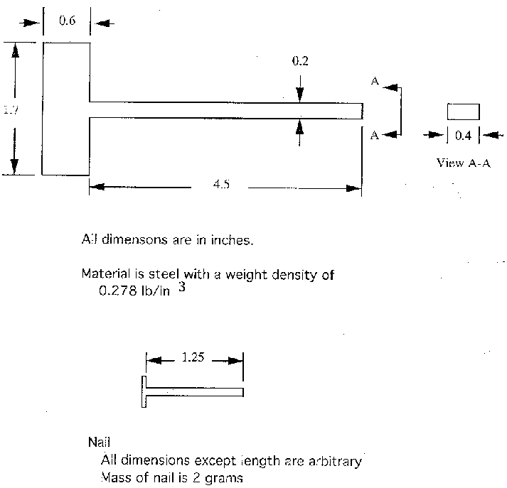
Figure 2 shows a schematic of a geometrically simplified version of the tool's piston with relevant dimensions, and of the nail. This information, taken from direct measurement of our sample nail gun, will allow you to calculate the mass of the piston. A simple measurement was performed in the laboratory to estimate the resisting force acting on the piston from the friction between the "O" ring seals and the cylinder wall. This was found to be approximately 20 Newtons during "quasi-static" motion. You will assume that this remains constant during the much more rapid motion of your simulation.
The piston is approximately 100 times as massive as the nail. The nail head is initially positioned 0.5 inches in front of the piston and 0.8 inches from the surface to be penetrated. Consequently, if the coefficient of restitution (shown as the elastic constant in your properties window) is non zero the nail will "fly free" ahead of the piston after the piston impacts it. We argue that the process of "tearing" the nail off of its carrying wires is so violent (often resulting in the wire disintegrating into tiny pieces) that this dissipates sufficient energy to warrant setting the coefficient of restitution to zero. If this is done for the nail then it will take care of both the impact between the nail and the piston and the subsequent impact of the nail with the wall. this is so because working model always uses the smallest elastic constant of a colliding pair as the effective coefficient of restitution.
Figure 3 shows the results of a test made by the manufacturer of the nail gun to determine the force acting on a typical nail as it penetrates a pine board. The significant features of this force profile to note are that 1) the force increases from zero, at the initial instant of penetration, to a conservative value of about 338 pounds at a time of 0.002 seconds later and 2) then the force remains essentially constant until just about the time of full penetration when it drops almost instantaneously to zero again. This leads to the idealized force profile shown in Figure 4. You will use this in your simulation, allowing for the possibility of an adjustable FMax, to account for penetration into materials of different density from that of a pine board. The equation for the force on the nail is given as
F=(if(body[4].v.x>0,if((t-input[17])<=.002,-(input[23]/.002)*(t-input[17]), input[23]),0.0))
(1)
and this force is active when t>=Input[17]. You will need to alter these expressions to place numbers appropriate to your system in the brackets identifying the body and the inputs. In this example body[4] is the nail, input[17] is the time, to, shown on Figure 4 when the nail is just about to touch the surface, and input[23] is the value of FMax.
Once the average force necessary to set the nail is known you can address the problem of determining an appropriate "accumulator" volume. To do this first divide the average force by the piston area to obtain the average pressure. Next assume that the expansion process driving the piston is isentropic. The isentropic exponent for air is K=1.4 and the appropriate polytropic process describing the expansion is
PVk = Po Vok
(2)
where Vo is the accumulator volume (the unknown to be solved for) and Po is the available supply pressure. Now the average pressure is given by

(3)
where A is the piston area and L is the piston stroke. This equation can be more concisely expressed in terms of two non dimensional parameters. These are Y = P(1-K)/Po and Ø = Vo/AL. This gives

(4)
If the supply pressure Po is say 50 psi, and taking K=1.4, the value of Y is known once the average pressure is known. This is a difficult equation to solve explicitly for f as a function of Y but may be solved easily by plotting Y vs. Ø (i.e. given a value of Y directly read off a value of Ø). Remember when you do this that typically Ø will be greater than unity.
In order to simulate the action of the energy absorbing safety bumper you will need to create a second Working Model simulation. Do this by modifying your existing file to eliminate the nail. Be sure to rename and save your new simulation. Next you need to create the "bumper" by using the spring tool. To do this attach two springs to the background and to two plates so positioned so as to replicate the spacing between the initial position of the face of the piston and the face of the bumper. Each spring is to be one inch long which is the thickness of the bumper. When you set these up make sure that both the "current length" and the "length" of each spring, as displayed in the property window are equal (and are both 1 in.). Other wise the spring will have some initial stored energy which will invalidate the simulation. These springs are to be located symmetrically with respect to the central shaft of the piston driver. Select the second order (i.e. x2) force deflection law for these springs and provide an input controller for the spring constants.
In reality the bumper is not attaced to the background nor are the plates mentioned really part of the actual design. However, the spring tool requires that springs be anchored at both ends. Because of this we will make convenient use of the background to provide one useful anchor, and use the movable plates as the second so that the "bumper" can deflect. The mass of these plates will have an influence on our simulation. Hopefully, if we take these masses to be sufficiently small their influence will be negligible. It is suggested that you use the mass value that the software automatically assigns to a newly created object as this will be many oders of magnitude less that that of the piston.
Repetitively run your simulation, each time varying the value of the spring constant, until you find a value that only allows the piston driver to penetrate the wood by no more than one eighth of an inch. This may turn out to be very tricky because in reality the bumper is very stiff; which means it will take very small time steps to distinguish between necessarily large values of the constant. Perhaps you might want to make a preliminary hand calculation of the constant to get yourself into the right range before running your simulation.
Summary of Problem Requirements:
Note: While executing the above simulations you should display some output meters that plot the kinetic energy and the momentum of components of the system. Think about what these show and how they relate to the principles of work - energy and impulse - momentum. Working model is not using these to solve the problem but you might. How? (You need not hand in an answer to this question so don't worry.)

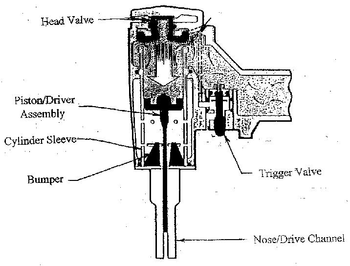
Figure 1. - Basic Elements of the Design of a Typical Pneumatic Fastening Tool

Figure 2. - Modeled Geometery and Dimensions of the Piston/Driver and a Typical Nail

Figure 3. - Example of an Actual Measured Time History of the Force on a Nail Being Driven into Wood

Figure 4. - Modeled Force Time History of a Nail Being Driven into Wood