

Objectives:
Apply the simulation package, Working Model, to simulate and evaluate various suspension
bridge designs.
Instructional Objectives:
Develop Working Model tools including pin joints, slots, rods, anchors, gravity, "Do not
collide" option, meters, applied forces, vector display.
Background:
Suspension bridges have become a very common method of bridge construction in the 20th
century. Examples include the Brooklyn Bridge (built in 1883 with a span of 486 m (1,600 ft)), the
George Washington Bridge (built in 1931 with a span of 1,070 m (3500 ft)), the Golden Gate Bridge
(built in 1937 with a span of 1,280 m (4,200 ft)), and the Verrazano-Narrows Bridge (built in 1964
with a span of 1,220 m (4,000 ft). These bridges all use the conventional suspension bridge design
where large cables (up to 3 ft in diameter) are suspended between towers and smaller cables are used
to "hang" the bridge deck from the larger cables (see Figs. 1 and 2). In a newer method, the
cable-stayed bridge (see Fig. 3), cables run directly down from towers to the roadway. Construction
of cable-stayed bridges has proven to be less costly than conventional suspension bridges. As a
result, this form of construction is becoming increasingly popular.
In this exercise, we will use Working Model to determine the forces in the cables of various suspension bridge designs. To achieve this, each student will be given the same span and bridge loadings and will be asked to design a suspension bridge. The bridge design consists of locating the towers and suspension cables at various points along the span. Then, three load conditions will be analyzed to determine how the loads are distributed amongst the cables.
Assignment:
Develop a Working Model simulation of a suspension bridge with a 1000 ft span. The span
will be idealized as consisting of 10 shorter spans, 100 ft in length, which are connected by pin joints
(see Fig. 4). Each of the 100 ft spans weighs 500 tons (1,000,000 lbs) and hence has a mass of 31,000
slug. At the ends of the bridge, roller supports are used to prevent vertical motion of the ends. Note
that these support conditions alone are insufficient to prevent collapse of the bridge (i.e. the span in
statically indeterminate). Hence, additional supports provided by the suspension cables are required.
Note that fixed anchor points near each of the roller supports may also be used. You are free
to select the type of bridge, number of towers, tower heights and number of cables in your design.
After developing the simulation, determine the maximum cable tensions for the following three load conditions:
To be turned in:
References
1. Troitsky, M. S., Orthotropic Bridges, Theory and Design, the James F. Lincoln Arc
Weldong Foundation, 1987.
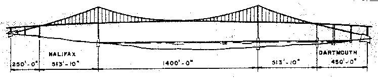
Figure 1. Typical Conventional Suspension Bridge -
A. Murray MacKay Bridge, Halifax, Nova Scotia (Ref. 1)
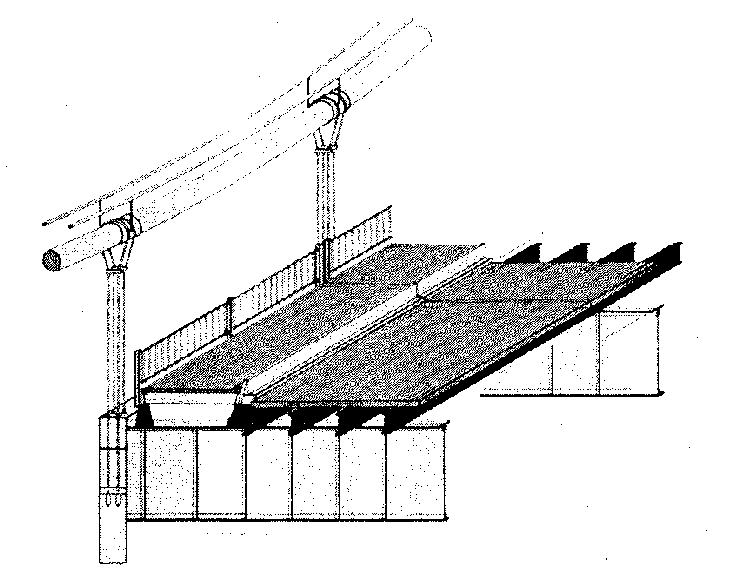
Figure 2. Schematic of Bridge Deck Support (Ref. 1)
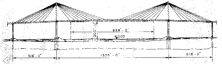
Figure 3. Cable-Stayed Bridge -
Saint-Nazaire Bridge, Loire River, France (Ref. 1)

Figure 4. Bridge Span to be Considered in this Assignment