

Objectives:
Apply the simulation package, Working Model, to determine the effect of
wind loads on cable tensions in structures supported by cables.
Instructional Objectives:
Develop Working Model tools including ropes (cables), anchors, generic
controls, meters, force field. Plotting in Excel.
Background: In many structures, cables loaded in tension are used to support loads. The tension in the cables are often easily computed using elementary mechanics. When wind forces become significant, prediction of the cable tension under varying wind conditions becomes more complicated. In designing such structures, clearly all load conditons need to be accounted for. As we will see, even if dynamic effects are neglected and the structure is allowed to settle into its equilibrium configuration for a given wind velocity, the cable tensions do not vary proportionally with wind velocity. In this simulation, Working Model will be used to determine the tension in a cable supporting a traffic light as a function of wind velocity.
In fluid mechanics courses, students learn that the drag force, F, induced by a fluid (in this case, air) passing around a moving body is given by
where p is the density of the fluid (p=1.2 kg/m3 for air at standard conditions), CD is the drag coefficient which depends in the body's geometry, A is the cross sectional area of the body exposed to the wind, Vw is the velocity of the wind and Vb is the velocity of the body. Note that if the body rotates, the area A (and consequently the drag force F) changes. For our simulation, we will use a drag coefficient CD=1.5 (appropriate for rectangular cross sections).
In Working Model, wind forces are modeled as a "Force Field". Under the World menu, the wind force is simulated by setting Fx to (using SI units)
where d is the depth (in meters) of the body and Input[~] refers to the control used to input the wind velocity. Note that the parameters "section(self,vector(1.0,0.0))" and "self.v.x" refer to the vertical section height of the body and the x-component of the velocity of the body, respectively. Note that we are neglecting the vertical component of the drag force which is much smaller than the horizontal component. Detailed instructions regarding setting up the wind force will be discussed in class.
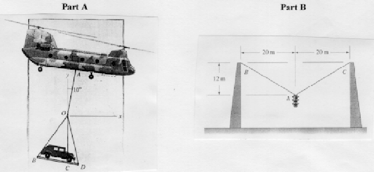
Part A (to be demonstrated by the instructor)
Consider the problem shown below (see Engineering Mechanics - Statics, by
Bedford and Fowler, p.118). Determine the tension in cable A0 as the helicopter
travels to the right at varying velocities. Simulate the load as a rectangular box of
dimensions 4 m x 1 m x 2 m (into the page) with a mass of 680 kg. Plot the tension
in cable AO as a function of velocity for velocities from zero to 25 m/s.
Part B (to be performed by students)
Consider the second problem shown below (see Engineering Mechanics -
Statics, by Bedford and Fowler, p. 98). Assuming that the wind travels from left
to right, determine the tension in cables AB and AC for increasing wind speeds.
Simulate the traffic light as a rectangular box of dimensions 0.75 m high x 0.25 m
wide x 0.25 m deep (into the page) with a mass of 140 kg. Plot the tension in cables
AB and AC as a function of velocity for velocities from zero to 25 m/s.

To be turned in: