Raccolta casi Working Model, visualNastran & SimWise - Innovative progressive suspension “Unit Pro-Link”,
Contatto Editoriale:
Paolo Lista,
Lista Studio srl®
Borgo Belvigo 33, 36016 Thiene Vi ITALY
tel/fax 0445,372479 o info@lista.it
AN INNOVATIVE PROGRESSIVE SUSPENSION “Unit Pro-Link"
Prof. Gabriele Virzě Mariotti and eng. Francesco Vitale (University of Palermo, Italy) present here an innovative progressive suspension “Unit Pro-Link”, by theory and by numerical simulation. The software MSC Visual Nastran is used for the verification of the analytical results. Besides the study is conduced in dynamical condition with the final purpose of a structural verify. The stress analysis on the several parts of the suspension is executed by FEM module, implemented in the multi body software. The stress evaluation on the entire rear suspension is executed trough a standard test (at double ramp), during which the excursion of the rear wheel axle achieves the end displacement position in a short time, and comes back. FEM analysis puts in evidence that the more dangerous configuration for the suspension is the end displacement and that the more stressed element is the equalizer, being the stress a few lower than the yield one, with a condition of limited life resistance.
The following is an extract from: Francesco Vitale; Gabriele Virzě Mariotti - Cinematic And Dynamic Analysis And Structural Verify Of An Innovative Motorcycle Suspension – 11° European Automotive Congress EAEC, 30 May, 1 June 2007, Budapest. Hungary.
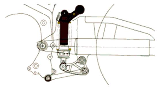
Fig. 1 – Progressive suspension UNIT Pro-LINK
1. Introduction
Dynamical vehicle behavior depends on the contact forces between tire and ground, on both the suspending and not suspending mass, which inertia is balanced by the forces in the suspension elements. The experience acquired by the firms has produced the definition of the suspension behavior: it has to be characterized by a soft reaction in the initial part of the compression and by progressive stiffening at the stroke end. Today the trend is the interposition of a lever system between the fork and the Spring - Shock Absorber Group (SSAG); the lever geometry produces the continuous variation of the ratio between the wheel displacement and the suspension compression.
The practical achievement is the plane articulated quadrilateral, with a different position of SSAG pivot, so that the possible suspension systems are the following:
Applications of the MB mechanism are not implemented in the market. No type, amongst the listed one, offers advantages respect to the others. The choice is has to be done in function of the available space, lowering the gravity center and the longitudinal inertia of the vehicle.
The rear suspension examined in this work is the set “Unit Pro-Link” (fig. 1); the difference with the classical Pro-Link consists in the connection of the shock absorber head with the superior truss of the fork instead than the rear chassis crossbar. In this way the shock absorber crushing is given by the displacement difference between two mobile points instead than a mobile point and a fixed one.
CINEMATIC ANALYSIS
The evaluation of the cinematic behavior of the rear suspension is done trough some dimensionless parameters, permitting the correlation between the vertical displacement of the wheel and the stroke of the shock absorber, in terms of loads and stiffness at ground. The implementation is done inserting the equations describing the geometrical and trigonometrical relations of the suspension in an electronic foil. The useful parameters for the calculation are:
Initial configuration of the cinematic system.
The parameters characterizing the set-up (vehicle attitude) are:
Besides the intervention possibility exists on the damping exerted by the shock absorber, in fact the braking regulation is foreseen in the more advanced types.
The complex chassis- fork – equalizer – connecting rod makes up an articulated quadrilateral, which remarkable points are shown in fig. 2.
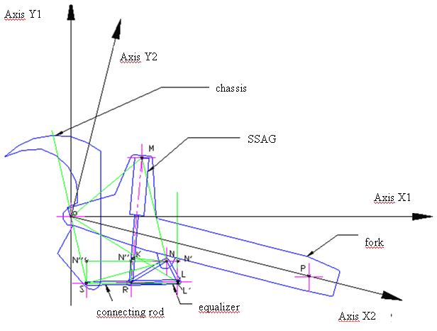
Fig. 2 – Articulated quadrilateral and remarkable points.
A very important parameter in suspension study is the ratio between the Wheel-Travel, in correspondence of the rear wheel pivot, Cv, and the Shock-Travel, DeltaLi, endured (1) by the SSAG:
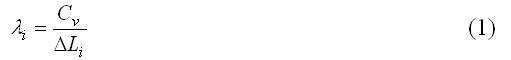
The Lever-Ratio (or Suspension Ratio) can be put in relation also with the fork rotation, besides the Wheel-Travel.
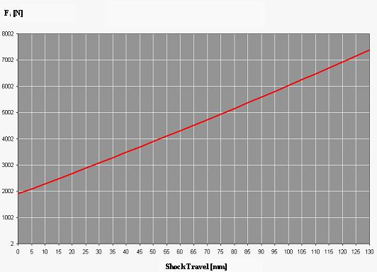
Fig. 3 - Force exerted by spring - Shock Absorber Group
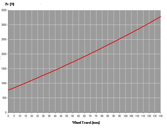
Fig. 4 – Course of wheel vertical force versus the excursion of the wheel pivot
The force exerted by the spring depends on the endured shock travel, DeltaLi, by the spring stiffness, (k= 95 N/mm), and by the initial travel, prc = 20 mm:

Fi depends directly by the shock travel DeltaLi that is function of the rotation angle of the fork; fig. 3 shows its trend versus the shock travel.
Of course the force exerted by the spring and vertical one acting on the wheel pivot are not equal, because the work of the vertical force has to be equal to one exerted by the spring:

so that the force normal to the ground, acting on the rear wheel pivot is given by:
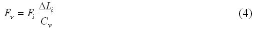
the trend is shown in fig. 4. This relationship also permits the determination of FV variation versus the rotation angle of the fork. The Lever Ratio is given by:
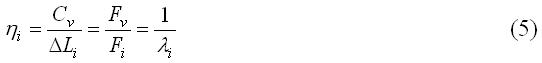
Fig. 5 shows the trend of the shock travel and of the Lever Ratio defined by (1). At last the wheel stiffness or “Wheel-Rate” can be obtained by the following relationship:
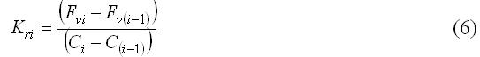
being i the index of the generic step.
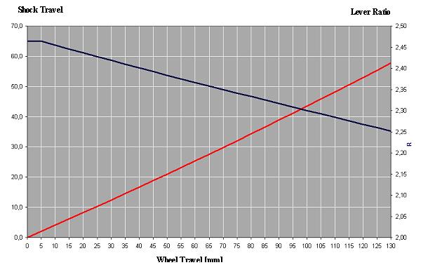
Fig. 5 – Shock Travel (red) and Lever Ratio (blue) versus the Wheel Travel,
in the progressive suspension Unit Pro Link
BUILDING THE CAD MODEL
Propaedeutic work.
Model construction is done by the “reverse engineering” (RE) technique, permitting the mathematical description of a physic model digitizing the surface. The RE use is rather advantageous in the memorization of existing models and objects, in the link between CAM/CAD methods and “rapid prototyping” for the design of CAD exemplar by implemented mechanism.
The preliminary phase consists in the collection of both the data furnished by the firms and obtained by object inspection, to take size and geometrical properties, but also the functional characteristics and the constructive solutions. The surfaces are successively mathematized as CAD primitives, verified and employed in the successive operations.
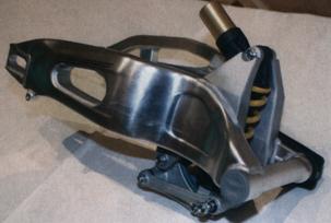
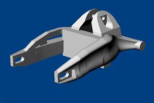
Fig. 6 – a) Photo of the rear suspension Unit pro link; - b) The fork assembled in Rhinoceros.
Fig. 6a shows the entire rear suspension, disassembled by the motor cycle; the connections of the fork pivot and ones by two connecting rods, verifying that the shock absorber is not connected to chassis, working inside the mechanism constituted by fork-connecting rods-equalizer. It is very complex; to redesign it the principal sizes are necessary: the firm furnished some measures and others are taken by a calliper. The design curvilinear profiles, represented by non-plane curves, are imported in CAD software.
Solid model elaboration.
The new generation of parametric programs is constituted by “feature based” software, as Solid Edge (SE), based on elementary working, as an extrusion or the revolution of a profile. Rhinoceros software combines the accuracy of the traditional CAD with the modeling flexibility based on the spline, permitting the draw of objects exploiting the NURBS (Non Uniform Rational B-spline) technology. The NURBS surfaces of free – form type, can accurately define a body, also having a complex form, i.e. the bodies with cavity. Besides Boolean operations on the solids are possible, permitting the obtaining of particular penetration and/or intersections with a certain immediacy.
The synergy of both the software produces undeniable advantages in the examined case: creation of the fork solid model in Rhinoceros room, creation of the other components in SE Part and assembly of the entire body in SE Assembly. The importation of the body in SE requires the use of an interchange file; the format Parasolid was chosen, because was believed more advantageous.
Fig. 6b shows the configuration obtained in Rhinoceros, and fig. 6c the final configuration obtained in SE.
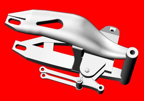
Fig. 6c - CAD model of the rear suspension “UNIT Pro Link”
CINEMATIC AND DYNAMIC SIMULATION RESULTS
CAD model is imported in MSC visualNastran 4D, by means of a transfer file, putting in the model the necessary constraints and loads to execute the simulation (fig. 7). VisualNastran permits the virtual prototyping, given that the cinematic system can be studied cinematically and dynamically, after the assembly of all the elements. The software resolves the motion equations considering perfectly rigid bodies. In particular the simulation is executed applying the external load to the fork by means of a linear actuator; the applied motion law is a double ramp, with linear variation of the wheel travel versus the time, to simulate simply the motion of the wheel on the road. Initially the cinematic simulation permitted the comparison with the value calculated theoretically, obtaining very close results.
In the dynamical simulation one has to take in account:
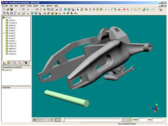
Fig. 7 - The suspension imported by CAD software and the wheel pivot drawn in Visual Nastran room.

Table 1 – Force and acceleration decrease, corresponding to an increase of the damping coefficient.
The value of damping constant is determined in several ways. By energetic consideration one reaches to the following relationship:
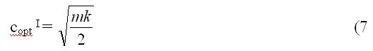
where m is the suspending mass, equal to the part of total mass that rear SSAG supports, then without the wheel mass and the connected parts (non suspending mass); k is the spring stiffness. Relationship (7 defines the constant damping value that does lower the maximum acceleration of the suspending mass, without to take in account the suspending mass and the tire stiffness, in the hypothesis of constant force applied to the suspending mass. This hypothesis is not near to the reality, so that the optimum value can be calculated in a more suitable way, considering the case of a sudden impact with the ground, by the following relationship:

this value is a few smaller than the previous obtained by (7.
Besides the value of optimum constant damping can be modified taking in account the stiffness kc of the tires:
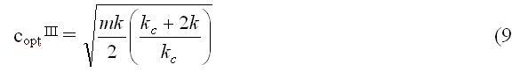
This relationship expresses that the damping constant has to be increased to mitigate the effects of the tire elasticity. The values of relationships 7-9 reach the maximum comfort, but the sports vehicles need more rigid adjustment.
Suspending mass of the motorcycle is equal to 197,7 kg, that is divided between the front part (53%) and the rear part (47%); the mass acting on the rear suspension is m = 92,9 kg. Assuming the spring stiffness k = 95 N/mm, the tire stiffness kc = 141 N/mm, the three values can be determined, obtaining:

By a theoretical viewpoint these values do not take in account the damper relative position respect to the wheel; to do it the introduction of the suspension ratio is necessary in the following way:
that is the (7 reduced at SSAG position. Given that the suspension is progressive with ? comprised between 2,25 e 2,46, one can assume a mean value ? = 2,355, obtaining a new value of the damping constant:

In this work the dynamic simulation is conduced considering the non-damping suspension and the suspension dampened by the four constant reported in (10 and (12.
Table 1 gives the simulations results for the maximum |FY| load and the corresponding accelerations, transmitted trough the wheel pivot to the chassis. They decrease with the increase of the damping coefficient: one can note that a decreasing trend of the transmitted force and of the acceleration corresponds to a damping coefficient increase. The minimum value of both the force on the SSAG and the maximum acceleration is obtained by the value expressed by (12. The simulations with a greater value show an increase of the maximum acceleration.
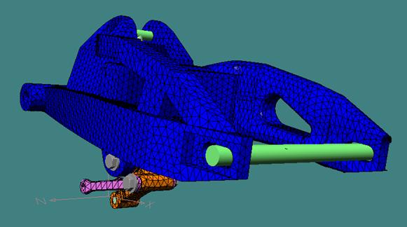
Fig. 8 –The suspension mesh (view point ľ rear, on the left side).
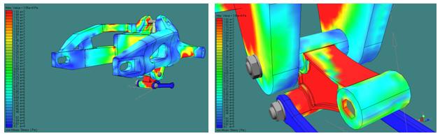
Fig. 9 – Von Mises Stress distribution during the more onerous stress
on the right particular of the equalizer, that is the more stressed element
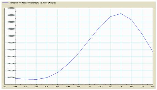
Fig. 10 – Von Mises stress in the fork (maximum stress) versus the time.
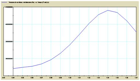
Fig. 11 – Von Mises Stress in the equalizer (maximum stress) versus the time
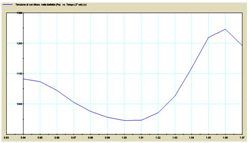
Fig. 12 – Von Mises stress in the connecting rod (maximum stress) versus the time.
Stress analysis
The stress analysis on the several parts of the suspension is executed by FEM module, implemented in the same multi body software visualNastran 4D. The stress evaluation on the entire rear suspension is executed trough a standard test (at double ramp), during which the excursion of the rear wheel axle achieves the end displacement position in a short time, and comes back. The purpose of the analysis is the evaluation of the highly stressed suspension elements. The worst condition is obtained achieving fast the end displacement position, when the fork reverses the motion to return to the initial position.
The adopted elements for the mesh have tetrahedron shape, which size is determined by the H – Adaptivity tool of visualNastran 4D (fig. 8). All the connections, the wheel axle and the upper and lower hinges of the shock absorber are considered rigid. Fig. 9 shows the stress map in the instant of maximum load.
The more dangerous instant for the suspension is the end displacement position, and the more stressed element (fig. 10-12) is the equalizer, with a maximum Von Mises stress equal to sigmamax = 408 MPa, (against yield stress sigmas= 505 MPa of aluminum 7075-T6); it is a static resistance condition with low value of the safety coefficient.
Because the fatigue solicitation has zero cycle, it does foresee a condition of limited life strength; in effect the equalizer is frequently substituted in the competition motorcycles.
CONCLUSIONS
This work was conduced following three guide lines: the first part has the objective to explicit the progressive characteristics of the suspension trough a cinematic study, developed in plane, leaving apart from the physical characteristics of the model; the second has a double purpose: the confirm of the results obtained in the first part and the observation of the solid model behavior in dynamical conditions for several values of the damping coefficient; the third part describes the mechanical solicitation trough the FEM analysis and the effectiveness of the followed redesign method.
The objectives of the three phases are reached: in fact the cinematic analysis highlights the progressive characteristic of the suspension; MSA (Multibody System Analysis) confirms the results of the previous, in lacking of damper in the two-dimensional model and shows that value of the acceleration transmitted to the chassis and to the driver is reduced increasing the damper constant, with benefits on the comfort and on the road-holding; FEM stress analysis indicates that the instant of greater stress on the suspension coincides with the end stroke, where the greatest acceleration are present, producing high inertia loads. The more stressed suspension element is the equalizer, and the more stressed zone of the fork coincides with the damper housing.
It confirms the validity of the redesign method (reverse engineering) and the potentiality of the dynamic simulation for the analysis of the suspension behavior, given that the parameters can be quickly changed to analyze the behavior, in particular the damping optimum constant value.
This analysis tool constitutes a valid aid in the design field, both in the project definition phase, helping to the constructive choice evaluation, furnishing an optimum alternative to the achievement of a prototype (rapid- prototyping), and in the design conclusive phase, simulating the indispensable road test.
REFERENCES
OTHER 83 DIFFERENT APPLICATIONS !
ALTRI 83 CASI IN SETTORI DIVERSI !