Raccolta casi Working Model, visualNastran & SimWise - visualNastran Pedestrian Model
Contatto Editoriale:
Paolo Lista,
Lista Studio srl®
Borgo Belvigo 33, 36016 Thiene Vi ITALY
tel/fax 0445,372479 o info@lista.it
DEVELOPMENT OF AN ANTHROPOMORPHIC MODEL
FOR VEHICLE-PEDESTRIAN CRASH TEST
Prof. Gabriele Virzý Mariotti and eng. Gaetano Bellavia (University of Palermo, Italy) are developing a simplified anthropomorphic model for the virtual simulation of pedestrian û vehicle crash test. ôDummyö construction in VisualNastran 4D allows for the preparation of crash test with several vehicle models. Its three-dimensional geometry is implemented by video animation software, extracting the geometry element for element, and its characteristics are in keeping with EURONCAP protocol. Every bodily segment properties (weight, mass center, inertia, etc.) are determined using the reference material on the movement biomechanics. Finally, fall tests from three different heights are simulated for the ôDummyö validation, obtaining a reliable result.
The following is an extract from: Gaetano Bellavia, Gabriele Virzý Mariotti: Development of an anthropomorphic model for vehicle-pedestrian crash test û XXI Science and Motor Vehicles 2007, JUMV international Conference with Exbition, 23-24 April 2007, Belgrade, Serbia, ISBN 978-86-80941-31-8
1. Introduction
Biomechanics of the impacts studies the human body movement and the injuries consequent to violent forces and accelerations acting on the several body parts, during car or air accidents. This branch of the biomechanics is the starting point of the passive safety that is the research of the methods to reduce the injuries. A direct connection exists between acceleration due to crash on the bodily segment and the caused damage; moreover the damage entity increases exponentially if the acceleration remains in the time, so that the time of constant acceleration is a fundamental comparison element in the study; i. e. the entire human body is able to bear accelerations until 30g, during 0,5 s, with a slight or reversible injury, while the internal haemorrhage risk and other serious injuries occur over 45g.
This work required a methodical study on the principal articulations kinesiology, to understand peculiarity and differences, with the purpose of the efficacious reproduction of the human articulations by making synergistically use of the available constraints in Visual Nastran. The skeletal complex and the muscles in their principal functions are substituted by constraints supporting the movement or limiting it in opportune way.
The problem of the articular friction is very efficaciously outdone; it is a notoriously complex problem in the case of Dummy models really produced to crash test. In the practice the reproduction of the same friction conditions of the human articulations trough the thin synovia liquid is very complex in general, while it is very simple and immediate trough the multi body simulation, inserting constraints with the correct setting.
Also in the simulation settings, the use of an anthropomorphic model cannot leave apart the validation tests of the results. In other words the model is subjected to forces or accelerations, measuring in opportune way its dynamical response, to execute successively the comparison with valid results.
A measure of the injury entity, consequently to a crash, is the value of HIC (Head Injury Criterion), today known in the entire world, correlating the acceleration level measured on the head gravity centre, with the duration time. Some free fall simulations are executed in Visual Nastran to test the Dummy model, differing for the Dummy initial position from the ground (1.5, 3 and 6 m respectively). This test is very similar to one executed on EUROSID models driven against rigid barrier. Test results are presented in the figures and reassumed in the tables, where HIC values are very close to results of other similar studies.
2. Model building in Visual Nastran 4D environment
In general, the multi body dynamic simulation software considers the model elements as rigid bodies, exchanging the reactive forces in correspondence of the imposed constraints during the assembly; it permits the use of more simple geometry to realize the model. In this study crash situations among the bodies are studied with the greatest possible accuracy with the purpose to preserve the original shapes limiting the computational load.
Fifteen bodily segments compose the Dummy model; they are constructed by video animation software, and imported in Visual Nastran room, in order to insert in the space all the bodily segments. The obtained Dummy anthropomorphic model is shown in fig. 1, where the several colours distinguish the fifteen rigid bodies.
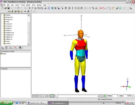
Fig. 1: Anthropomorphic model on visualNastran 4D desktop
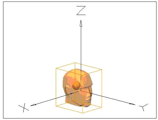
Fig. 2: Position of the head mass centre.
Hands were excluded in the model; this choice, according to the standard procedure of the crash test, is due to the fact that they assume a very casual position during the test. The hands are constituted by very complex articulations (27 bones are present) with very high difficulty of reproduction; non-justified given that they are not vital parts of the body. Besides the hands are light and offer low resistance to the crash, so that their dynamic contribute to the test can be neglected.
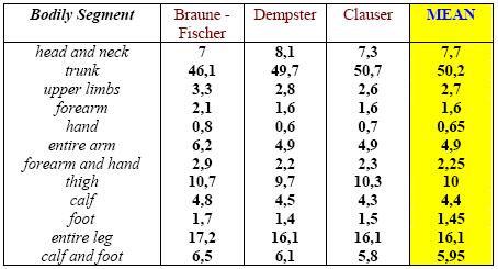
Table 1: Bodily segments mass [kg].
2.1 Weights and masses
A long research of study in the matter was executed to attribute correctly the mass to every bodily segment constituting the model, to reach an inherent result to reality. The several studies in literature give different results in term of weights, without metrological standard and rigorous statistical approach. Moreover many studies give the values of a whole of bodily segments.
The only imposed constraint in this work is the Dummy mass equal to 75 kg. It is one corresponding to the 50th percentile of the European adult population, used for the crash test executed in Europe; the extrapolated values of the bodily segments are obtained applying a weighed average to the values of three selected studies during the last decade, respectively of Braune - Fischer, Dempster and Clauser (table 1). The studies were executed weighting bodily segments obtained by dead bodies, sectioned in correspondence of the more important articulations. Table 2 shows the values extrapolated for the fifteen segments and inserted as input data in Visual Nastran. One can verify that the sum of the bodily mass is equal to 75 kg.
2.2 Mass Centre and Inertia Moments
Visual Nastran permits the calculation of the mass centre position, inserting as input the specific weight and the solid geometry of the body. This possibility is not used, because the mass distribution is not homogeneous in the human body: i.e. the thorax has more organs inside (hearth, lung, part of the intestine, etc.), a complex skeletal apparatus, blood and physiological fluids. The research in literature returns the position of every segment mass centre: Dempster studies on dead bodies are taken as reference. Fig. 2 shows the position of the head centre highlighted by a spot.
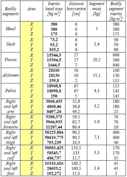
Table 2: Bodily segments mass and inertia moments attributed to Dummy model.
VisualNastran 4D application needs an only reference system for all the segments, chosen in correspondence of the head barycentre. On the base of the inertia moments tabled by Dempster, the values, regard to the new reference system, are calculated by Huygens û Steiner theorem and are reported in table 2. The calculation of deviation moments is calculated, frame by frame, by the software during the simulations.
2.3 Articular joints
The same Dempster believed that the bodily segments are recognized in the limbs, when the segments have an angular variation one another or when skin creases are presents; in the other cases the location of the articular joints is not simple, i. e. in the case of the muscles interesting more bodily segments. Besides articular rotation axle moves when the parts are in movement in the space, so that Dempster parameters are used to individuate them, while their displacements are considered negligible with good approximation, this assumption being done in all the biomechanical studies.
Numerous tables in the literature reports mean values of the friction coefficients among the articulations. In general they are very low, assuming value between 0,004 and 0,02; a mean value of friction coefficient is chosen equal to 0,012. The articular joints are implemented reducing the number of variables and simplifying them substituting the complex joints of the human body with the constraints of Visual Nastran dynamical library.
The construction of dummy models, for the real crash tests, require the use of expensive materials, or particular lubrication set, because used materials for both the prosthesis construction and the implementation of crash models do not easily offer enough low friction coefficients.
2.3.1 Neck articular joints
The neck articulation is implemented substituting to the whole of the neck articulation two constraints, permitting all the three neck movements, around three orthogonal axes (fig. 3). A constraint revolute joint is inserted in the position corresponding to the first occipital vertebra, with a limit of the rotation around the x-axis. A constraint spherical joint permits the rotation of the occipital vertebras, in correspondence of the 6░ vertebra position.
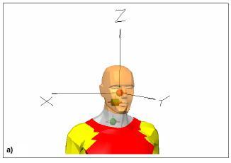
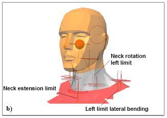
Fig. 3: a) = Neck articulation; b) = Rope constraints.
The rotation limits of the spherical joint may not be inserted as for the revolute joint, because Visual Nastran does not permit it. The implementation needs the limit angles that the head can assume with regard to the rotations around the three axes; it was obtained inserting six constraint of rope type, permitting the definition of the lengths corresponding to the minimum and maximum extension, analogously to the muscles action. Fig. 3b shows three rope constraints, missing the symmetric ones.
2.3.2 Shoulder articular joints
Shoulder articulation is not much interested by the pedestrian û vehicle crash test; it is interested with the body, but it opposes to the crash in a quasi-rigid way. In other words, it is interested to the crash, but has not the possibility to perform its function. It is not a part of vital importance of the individual, besides the human instinct reaction of head protection, making shield with the arms, has not to take in consideration due to the slowness of the action respect to the crash time. Taking in account these considerations, the possibility of the articulation motion (bending û extension) is permitted inserting a constraint revolute joint around the x axis. (fig. 4). This choice allows the rotation possibility to the arm, so that it returns the inertia effect to the body going away from the body axis. The choice is in agreement with the anthropomorphic models of the bigger building cases; in some tests both the arms are tied up the wrists.
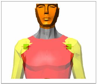
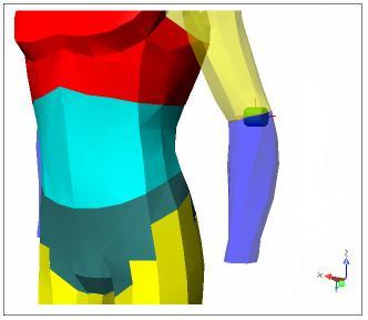
Fig. 4: Shoulder articular complex. - Fig. 5: Elbow articulation.
2.3.3 Elbow articular joints
Elbow is an articulation giving the possibility of two types of different movements: prone û supination and bending û extension. For the purposes of this work the rotation movement around the elbow axis is neglected because it is considered not much influent and secondary in the test, with regard to the bending û extension (fig. 5). A constraint revolute joint around the x axis is inserted (fig. 5), limiting the angular movement.
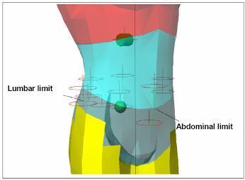
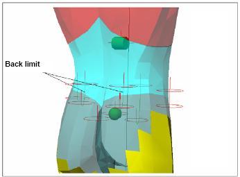
Fig. 6a: Abdominal articular constraints and limits. - Fig. 6b: Lumbar articular constraints and limits.
2.3.4 Trunk articular joints
Combinative action of both the spinal column and the muscles permits a remarkable mobility and a sure constancy of the equilibrium state to the human body. The simulation of the behavior of the entire column requires numerous constraints.
In particular the neck articulation (1░-7░ vertebra) is considered resolved in the previous 2.3.1. A revolute joint is used to simulate the thoracic vertebras (8░-19░), inserting angular limits of the movement in analogous manner. A spherical joint is inserted to simulate the lumbar part (20░-24░ vertebra), as fig. 6 shows. The mobility of this last articulation requires the reproduction of the muscles set governing the abdominal zone: the numerous muscles bundles are substituted with five rope constraints. Fig. 6 shows the insertion of an extensor constraint, in front position (abdominal right muscle), two extensor constraints on the sides (lumbar oblique muscle) and two extensor constraints on the back, to simulate the thoracic lumbar bundle.
2.3.5 Hip, knee and ankle articular joints.
A spherical joint should represent the complex articulation of the hip. Nevertheless any consideration has to be done: the use of a multi body software as Visual Nastran foresees the solution of the motion equation by the calculation of a certain number of unknowns, depending on the system freedom degree. It may be reduced discarding some motion possibility of the system, with the purpose of reduction of the computational load. In this work, for the test type, the movements of hip rotation and others of lower importance are neglected, letting the possibility of extension and bending. Thus the revolute joint in fig. 7a is introduced and the application is simplified for the immediate definition of a working angular domain; the application should be more complicated inserting a spherical joint constraint, given that Visual Nastran does not permit the definition of an angular domain on it, having to use numerous other support constraints to limit the leg movements.
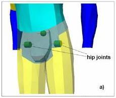
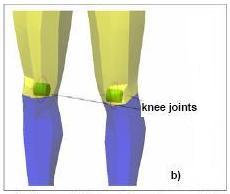
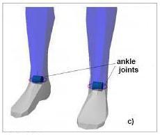
Fig. 7: Articulations of hip (a), knee (b) and ankle (c)
Because the knee rotation is permitted in determined conditions only, this movement is defined secondary and surely non-influencing the test. The knee articulation (fig. 7b) is simulated with a revolute joint; a motion angular limit is introduced in order to permit an angular movement equal to û135░ and an extension movement equal to 0░. The ankle articulation governs the foot and the leg motion. It has two freedom degrees and permits the bending movement, while other movements, that are fundamental in the pace approach, are neglected for the test purpose, given that, in the pedestrian û vehicle crash, the test starts with motionless model loaded by a forces system that does not act on this bodily segment. The ankle articulation is simulated by a revolute joint (fig. 7c), permitting the movement of the feet around the ankle with a sole rotation movement equal to û50░ and a back rotation equal to 20░.
3. Confirmation test of the Dummy
3.1 Injuries scale and criteria
The function of the vehicle retention systems and absorbers is the reduction of the provoked injuries. For this reason the knowledge of both the damage and injuries mechanism developing on the human organs and tissues is extremely important: it is the basis of the engineering interventions to improve the efficiency and the protection offered by the vehicle safety systems. The practical exigency to assign a numerical value at every injury, in order to have a classification of the injury seriousness, brings to the introduction of injuries scales. They are distinguished according to structural type injuries (fractures) or modification of organs functionality, more than the characteristics of temporariness or permanence of the suffered damage.
The Anatomic Injury Scale AIS classifies the injuries versus their seriousness; an entire number is associated with every level of the scale, which corresponds to a certain grade of critical damage (tab. 3).
Empirical injury criteria are based on the linear acceleration and on the forces acting in certain measurement points during the crash. They can be reassumed as follows:
The availability of a valid criterion improves the knowledge of the injury mechanism and of the situations determining it. It permits the correlation of the load values during a crash with the opportune values of the injury scale.
Several risk criteria are formulated for several body parts. The more spread for the damages evaluation are: HIC (Head Injury Criterion) and GSI (Gadd Severity Index) for the head; TTI (Thoracic Trauma Index), VC (Viscous Injury Response) and 3MS (3MS Criterion) for the thorax, and others used for the neck, thighbone and tibias.
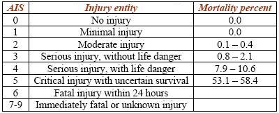
Table 3: AIS Scale of injury entity and corresponding fatality percent [11][12].
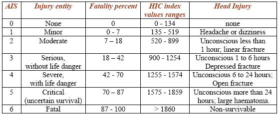
Fig. 8a: Wayne State Tolerance Curve (WSTC).
3.2. Damage criteria for the head
First criterion of the human tolerance level to a head impact was the Wayne State Tolerance Curve (WSTC) shown in fig. 8.
It puts in relation the linear acceleration level with the duration of an impulse yielding an injury of equal seriousness, in the case of crash with head contact. It represents the separation line between the zones of skull damage and no; the injury threshold corresponds at every point. The experimental data considered for the curve draft are:
Remarkable difficulties remains in the acceleration determination during the entire time interval; to exceed this problem GSI (Gadd Severity Index) criterion was set on 1966, expressed by the following relationship (1):
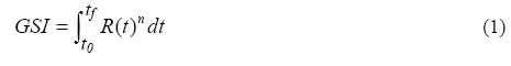
Where:
The tolerance threshold proposed by Gadd, for crash with impact, is equal to 1000: the overcoming of this value indicates a greater probability than 95% of extended concussion. The HIC (Head Injury Criterion) is a new injury criterion for the head, today acknowledged in the entire world. It is based on a careful analysis of the experimental results, relatively to the answer of the skull at an impact against a rigid wall, considering as damage indicator the presence of linear fractures, with life risk. The mathematical relation expressing HIC criterion is (2):
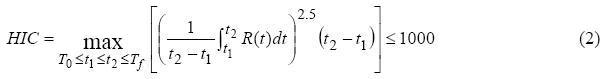
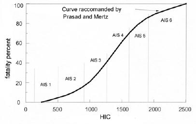
Fig. 8b: Probability of fatality versus HIC
Where t1 e t2 represent respectively the initial and final instant of a time interval, in seconds, during which HIC assumes the maximum value; the amplitude of this interval is conventionally equal to 36 ms. On the experimental curve, built with the experimental values by accelerometers, a mobile time window of 36 ms is applied, the corresponding HIC value is calculated for every interval, the searched HIC value is the maximum amongst calculated values. Also it is limited by threshold tolerance: one has the concussion risk if HIC is more than 1000. The value 1000 identifies a strong seriousness accident and corresponds to AIS > 4, HIC value equal to 2000 corresponds to a greater AIS value, but not equal to double (Tab. 3, fig. 8b). The limitations to HIC criterion are the following:
Today HIC is the more widespread criterion for the evaluation of the head damage in consequence of a crash.
3.3 Choice of the confirmation test
A vast research, on the possible ways to test the model, gives the result that a reference rule does not exist today, given that EURONCAP rules are in approval course. The firms producing pedestrian dummies execute on them numerous tests, compared with the data coming by other biomechanics tests executed on voluntaries or dead bodies. They divulge the results only to costumers, the vehicle firms, to demonstrate the good quality of the offering product. In this paper the validation of the Dummy is executed by Biomechanics study recognized by the major experts in the matter.
Draft in fig. 9 is put as reference, correlating the fall down of a man trough a curve of WSTC type; the entire lines represent points at constant acceleration expressed in g. The draft is obtained by test with body in supine position, with forehead turned toward the bottom, with the accelerations measured in the head gravity centre, in a crash with a plane (usually the barrier is implemented in concrete). This test is very suitable, because the Dummy is tested in its whole and with the maximum interaction amongst the entire body elements and the impact barrier. The literature describes the tests executed on other anthropomorphic models as the dummies BioRID P3 and Hybrid III, subjected to the same test of rear impact of the head at several velocity values. These models born as vehicle passengers, but the exclusive room (the head crash) are inherent and common with the pedestrian case.
3.3.1 Dummy Validation test: crash due to fall and impact with the ground.
The objective of fall test is the insulation of the model behaviour by each other factor that could distort the test result; it is similar to ones done in general on the dummies. The fall tests are simulated in Visual Nastran, and are distinguished one another by the initial distance of the Dummy from the ground, 1.5, 3 and 6 m respectively.
Fig. 9: Draft fall û duration under constant acceleration.
This fall test imposes impact velocity with the ground that is comparable to one suffering by the dummy during the pedestrian û vehicle crash test. The accuracy grade of test execution, compatibly with the computational time, is chosen in function of the same modality of the tests. In fact a number of rate frames per second is chosen equal to 500; the step number, executed in the surrounding of a single frame, is put equal to 5. In this way the simulator repeats the integration calculation 2500 times in one second, so that the time integration is:
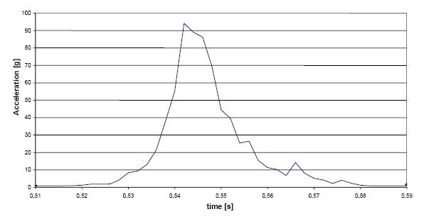
Fig. 10 a: Head barycentre impact acceleration measured in a fall from 1.5 m.
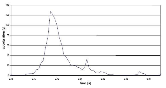
Fig. 10 b: Head barycentre impact acceleration measured in a fall from 3 m.
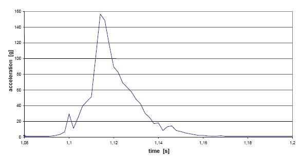
Fig. 10 c: Head barycentre impact acceleration measured in a fall from 6 m.
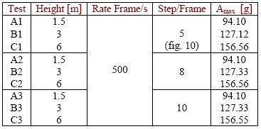
Table 4: Fall test data synthesis.
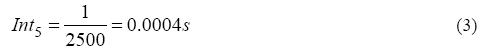
Relationship (3) gives a time interval believed sufficiently valid for the simulation, if the time of constant acceleration is presumed 0,01 s about. Fig. 10 shows the acceleration values, measured in the head along the three coordinate axis of the global system in Visual Nastran, for the height of 1.5, 3 and 6 m. The fall tests over 6 m are not reported because the impact velocities with the ground are greater than one of the pedestrian vehicle crash test; i. e. the impact velocity in a fall test from 9 m is equal to 15 m/s about that is greater of 20 % than the velocity of the anthropomorphic model during the crash test. However some tests at 9 m have shown a sufficient reliability; the result accuracy increases to increase of the chosen step/frame, any time giving unexpected results. The whole of values obtained with fall from 9 m is positioned (fig. 9) in the area of very dangerous car accident, at the limit of the individual survival to the impact. The biomechanics refers that the forecasts and the calculations are very more uncertain and the damage estimate are very less reliable, because the crash is characterized by a great number of bone fractures and of tissues damage.
The graphs in fig. 10 show the pick acceleration value, the time in fraction of seconds is reported in abscissa, while the value of the acceleration in multiple of g is reported in ordinate, in the global coordinate system of Visual Nastran. The graphs are obtained with a number of step/frame equal to 5.
3.3.2 Computational validity
Table 4 shows the data obtained by the three tests, respectively with a number of rate frame per second still equal to 500, but a number of integration steps equal to 5, 8 and 10. Following the same reasoning of relationship (3), the time intervals of constant acceleration are, for 8 and 10 integration steps, as in (4):

The analysis of the results shows that a great number of step/frame has not a great importance, because the last column of table 4, obtained by direct data estimate, does not show variations. This result has very great interest because the calculation time is decupled passing by 5 to 10 step per frame.
4. Comments and conclusions
Inserting the data of table 4 in the graph of free fall (fig. 9), one can note that the dispersion around the areas corresponding to expected values is very satisfactory (zone A, B, C marked in red for the three different tests). The values, obtained by fig. 10a, show that the acceleration pick is very high; with permanence enough protracted of 0.055 û 0.06 s. The head has acceleration equal to gravity one before the impact, and in the interval of few hundredths of second achieves the pick value equal to 94.1 g (this value remains for 0.004 s only).
Analyzing the graphs of the fall test from 1.5 and 3 m, one can note a moderate increase of the acceleration pick values, with an increase of the mean duration of the impulse: the permanence time of acceleration can be estimate in 0.0075 s in the impact from 3 m. The free fall graph permits an estimate of the probable caused damage, the fall from 3 m (B) is more dangerous than one from 1.5, but the differences are not so marked. The fall from 6 m presents an impulse permanence of the similar duration, but the acceleration pick is very stronger; this value is disposed out of the zone of certain survival, between the lines corresponding to an acceleration of 10 g and 100 g in fig. 9.
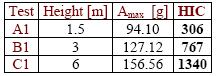
Table 5: HIC by free fall test.
Each curve of fig. 10 can be useful to calculate the HIC value characterizing the tests. The relationship (2) can be applied singularly to the tests, by making use of Excel, to integrate the acceleration values respect to the time. The integration window is put equal to 0.036 s and the integral is calculated with progressive step 0.002 s. HIC value is the greatest obtained value, corresponding physically to the greatest area subtended by the curve in an interval of 0.036 s. Table 5 shows the results for the three examined cases.
Another subjective comparison can be done between the highest HIC value for the free fall test from 6 m, with the factors of anatomical scale AIS (tab. 3), trough fig. 9 one can conclude that a factor AIS equal to 4 can be attribute to the test C1, it comports extended seriousness damages to the individual, with life danger. At last HIC calculation is executed for the free fall test from 9 m. The acceleration pick is 180.36 g, the permanence is 0.004 s, the result is HIC = 2421, that confirms the expectative.
REFERENCES
OTHER 83 DIFFERENT APPLICATIONS !
ALTRI 83 CASI IN SETTORI DIVERSI !