Raccolta casi Working Model, visualNastran & SimWise - Simulatore di moto ad alta frequenza

Contatto Editoriale:
Paolo Lista,
Lista Studio srl®
Borgo Belvigo 33, 36016 Thiene Vi ITALY
tel/fax 0445,372479 o info@lista.it
SIMULATORE DI MOTO AD ALTA FREQUENZA
Getting a new idea onto the drawing board can be fraught with problems. If a concept is truly different, which it has to be to contribute meaningful benefits, then it can be difficult to prove that it's viable -- especially without adequate resources. And getting scarce resources allocated without proof of concept can be equally challenging. It's the proverbial chicken or the egg question in an engineering setting.
Increasingly, engineers are turning to mechanical simulation software for proof of concept, producing a virtual working model that demonstrates to management and customers how the concept will work. An example in progress is the High Frequency Motion Simulator (HFMS) for the Air Force Research Laboratory (AFRL) Kinetic Kill Vehicle Hardware-in-the-Loop Simulation (KHILS) Facility.
The HFMS is being developed by Dearborn Gage Company, a leading manufacturer of precision gaging, inertial test systems and flight motion simulators (FMS) with over 60 years of experience. This device is designed to improve KHILS capabilities in its goal to accelerate development, integration and deployment of enhanced guidance and control systems through accurate, repeatable laboratory tests, thereby reducing the number of flight tests required for verification of system performance and design integrity. Motion simulation is an integral factor in the test of these systems. Typically, a three-axis gimbaled instrument is used to perform the rotational motion of the missile with an additional two outer gimbals (equipped with an appropriate target scene projector) integrated to provide a dynamic element for target motion and sensor tracking.
One objective of the government's KHILS facility is to support the development of missiles that intercept and destroy enemy missiles. Advanced interceptor systems (defensive missiles) typically use reaction jets for divert/attitude control, which can induce very high frequency dynamic motion in the form of airframe rigid body response or vibration. With increasing accuracy requirements for defensive missiles, the impact of high-frequency sensor line-of-sight errors on missile closed-loop guidance is a critical testing issue. By accurately simulating the missile encounter environment, it is possible to identify these errors and correct them before an actual flight test is ever performed.
A persistent limitation in present day simulations is the bandwidth of the FMS. This is the result of the pitch and yaw gimbals not being capable of producing the required dynamic response and limitations in the compressibility of the hydraulic fluid used in a traditional actuation systems. Mr. Bob Peterson, VP Engineering/ATS Marketing and HFMS Program Manager for Dearborn Gage Company, explains, "The most advanced flight motion simulators currently available have bandwidths of 60 Hz. This is a limitation in the response spectrum that can introduce artifacts into hardware-in-the-loop simulations in the form of modified control system duty cycle, which could lead to questionable test results."
The HFMS presents a difficult design task, since it ideally must simulate missile body motion in six degrees of freedom (DOF). The HFMS is being developed to emulate the rotation of the missile (roll, pitch and yaw) and the flight translation (X, Y, and Z) due to vibration of the missile body. Mr. Peterson explains, "One of the problems we face is how to quickly develop a dynamic model of this system that will accurately characterize the vibration introduced by the airframe dynamics (0-1000 Hz). The most important hurdle to overcome is the design of a suitable gimbaled/suspension system that will satisfy the structural properties necessary to design a closed-loop control system exhibiting 1000 Hz bandwidth. In the case of a 6-DOF device, it's very complicated because it requires rotation and translation equations. This makes it a tedious process."
A preliminary kinematics/dynamics model was developed in MSC.visualNastran 4D to determine the required properties of the system actuators. "This model provided the platform to determine the force and displacement requirements of the six HFMS actuators," said Peterson.
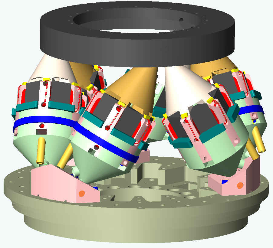
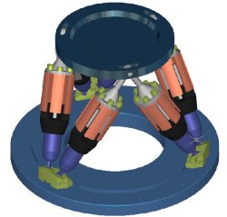
The HFMS is a lightweight, rigid structure with a motion platform supported by a three-dimensional rod-to-pivot suspension system, which is incorporated into a multi-axis linear motion actuator as shown in Figure 1. This type of active suspension is able to perform axial and radial motion of the payload with 6-DOF. According to Mr. Peterson, "MSC.visualNastran 4D accelerates the entire process of analysis and design. It enabled us to build a virtual model of the system, including the platform, missile G/C, and six actuators that are used to impart the motion. This project required a week to put the proof of concept together."
All of the elements required to develop a physical model are resident and easily applied within the software (S/W). "Easy, even for electrical engineers," quoting Mr. Peterson. The actuators can be activated with various modes such as position, velocity, acceleration, or force. This feature provided the tool to quickly determine the force and displacement requirements of the actuators that would be needed to satisfy the dynamic requirements of the motion platform. Tests were executed using the model in a zero-force actuator mode with external forcing functions, i.e. external forces or torques, to determine displacement and force requirements for the actuators. The actuator mode was then changed to position mode and instrumentation added to each actuator to determine force requirements to replicate the externally applied forces and torques. The metered data were then transferred to a Microsoft Excel spreadsheet for analysis. Mr. Peterson says, "After the initial 'cockpit problems' associated with a new S/W tool, the analysis and modeling effort accelerated and resulted in a successful effort. Parametric analysis was completed in record time and greatly increased the confidence in the development. Certainly the dynamic modeling of such a system is a formidable problem, and I can say that this tool SAVED man-weeks of effort."
A typical data set obtained from the model is shown in Figures 2 through 5. The forces applied to the platform were obtained from experimental data and input to the appropriate axis of the model. The resulting angular displacement, velocity and actuator forces were then metered and recorded for analysis.
The torque required to produce a load angular acceleration to the pitch axis of the platform was simulated, and the resulting actuator force and displacement were determined from the model. A unique feature of the software is its capability to interface to MATLAB/SIMULINK. This feature is currently being tested and certainly will accelerate the control development.
"We were able to create the HFMS model in MSC.visualNastran 4D like someone would build a tinker toy model, only on the screen as a virtual model," said Mr. Peterson. "It enabled us to simulate the 6 DOF model of the missile body."
The seeker mechanism of a missile is mounted on the HFMS so that it can experience the motions or angular degrees of freedom. Mr. Peterson explains, "The seeker sees a synthetic target that represents the intercept condition. Programmed equations that represent the engagement area are maintained by an array of computers. The missile is launched. The seeker searches for the target. It finds the target and tracks it. The target moves dynamically, like a ballistic missile. If the target is hit, it's a win. If not, the miss distance is computed, hopefully it's small."
"Now that I'm familiar with the software, I can build this model in a matter of hours," said Mr. Peterson. "It took several man-weeks to develop and model the equations of motion for the HFMS. Literally, that's man-weeks to man-hours." Based on the average senior engineer's salary of $75K annually, three weeks equals $4,326 and a half-day equals $150. That's a saving of $4,176 hard cash, which pays for the software. However, the cost of errors due to manual calculation of equations can be enormous, and this can have a substantial effect on manufacturability and after sales support. Additionally, the cost of a three-week delay in proof of concept could mean loss of the project to a competitor.
ALTRI 83 CASI IN SETTORI DIVERSI !