Contatto Editoriale:
Paolo Lista,
Lista Studio srl®
Borgo Belvigo 33, 36016 Thiene Vi ITALY
tel/fax 0445,372479 o info@lista.it
IL VISUALNASTRAN AIUTA UNA VETTURA PER DISABILI A SUPERARE IL TEST DELL'ALCE
Il team del prof. Gabriele Virzì Mariotti del Dipartimento di Meccanica dell'Università di Palermo aiuta la Guerrera a sviluppare con il visualNastran 4D una vettura per disabili più sicura.
JUMV - Automotive Engineering for Inteligent Vehicle Systems
YU – 03022 Dynamic Simulation of Behaviour of a "Light Vehicle" for Disabled Users, Tested on a Virtual Road
Stefano De Gaetano, Mechanics Department Palermo University, Palermo, Italy
Giacomo G. A. Guerrera, Individual Enterprise Ing. Giacomo Guerrera, Messina, Italy
Gabriele Virzě Mariotti, Mechanics Department Palermo University, Palermo, Italy
ABSTRACT
In this paper the numerical simulation of the behaviour on the road of a light vehicle to disable users is executed. One begins with the examination of the suspension geometry and of the characteristic angles of the wheel. During the first simulation phase the damper optimisation is executed: a vehicle is schematised like a suspended mass acting on the ground by four non-suspended masses, including the wheel and the suspension. Three different vehicles have been tested on this virtual route, each one equipped with a particular damping constant. The second simulative phase has the purpose to test the vehicle reaction to the virtual driver manoeuvres (Alce test with modifications). It allows modifications of some suspension parameters, offering the chance of testing the differences on the virtual track. The tested vehicles are equipped with two different geometrical configurations with different damping coefficients. Hence the wheel-ground reactions are determined and torsion rigidity analysis is executed.
KEY WORDS: Numerical simulation; light vehicle, constant damping, suspension ratio, Alce test
1. INTRODUCTION
A light four-wheeled vehicle is a particular one (about art.52…), destined to the transportation of human beings, subjected to particular rules regarding limitations about construction and security. A lot of these rules are about the use of particular materials and the economy of these choices, other rules are about the components industry like the anterior and rear lights and the right disposition of the inside lights.
The geometry of a light four-wheeled vehicle is internationally ruled as follow:
Max weight : 350 Kg + a max load (200 Kg)
Max engine power : 4KW
Max speed : 45 Km/h
The stationary brake has to be able to block the car on a 18% ramp
Max strength on the pedal : 350 N
Max length : 4,00 m
Max width : 2,00 m
Max height : 2,50 m
The vehicle, studied in this work, has been created to give a mechanical freedom to those who are without a natural freedom. During this work we will discuss the geometry of the suspension, with particular regard for the better configuration of the characteristic angles, trying to support the ethical attempt of the project: “offer a mechanical solution to a natural problem”.
After the initial description of the right configuration, the virtual components, created and assembled using a CAD system, will be described and later transferred to the VISUAL NASTRAN 4D software for the next simulation that will be realized to find the better compromise between the dynamic stability and the ride comfort. There also will be a virtual test of the vehicle along a kind of obstacle route, for two different four-wheeled vehicles equipped with the same kind of damper but with a different longitudinal geometry of the lower bracket of the suspension.
Vehicle geometry
Figure 1 shows the vehicle geometry, with a particular attention for the right position of the barycentre. The rough chassis showed gives only the idea of the base design profile. Basing the initial considerations upon past results and respecting the international rules described, it is possible to assign to the non-suspended mass a weight of 18 Kg and 280 Kg to the suspended mass, including the engine and the transmission elements.
The anterior traction vehicle is equipped with a LOMBARDINI FOCS DIESEL LDW 502 engine, which is able to produce 13,4 HP without wringing, using MICHELIN 145/60/R13 tyre with a radial body with the following instructions:
Track: 145 mm
Aspect ratio : 60%
Nominal diameter : 13’’ (330 mm)
The wheel diameter has been increased in the imposed tolerance to obtain the right longitudinal disposition of the tyre and is D=511 mm, leaving a steering room of 44,2mm.
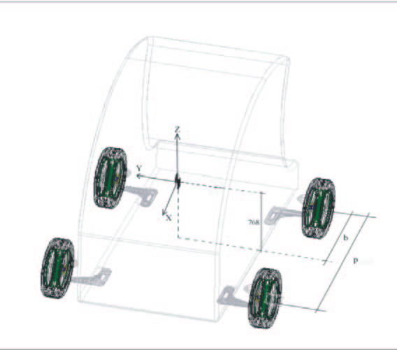
Fig. 1 – Barycentre height and vehicle geometry
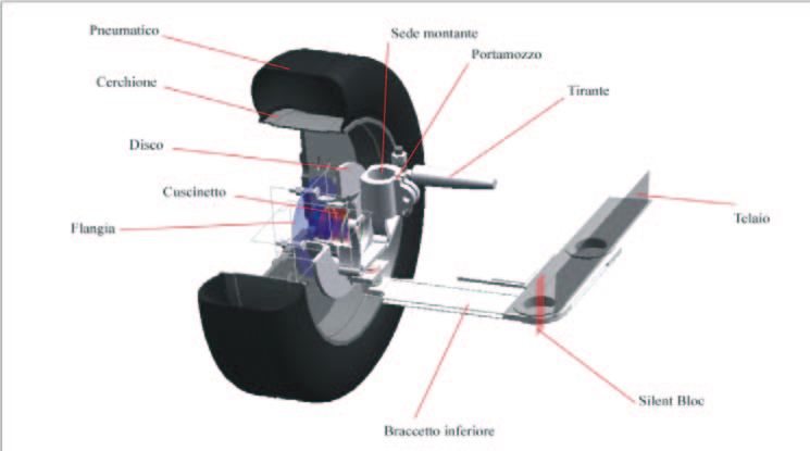
Fig. 2 – Lateral view in section of Mac Pherson suspension
Suspension geometry
The suspension scheme is like a Mac Pherson one and is illustrated in figure 2. This scheme derives from a quadrilateral geometry in which the superior transversal bracket-system is substituted by a vertical stud joined to the damper-spring system [5], a solution developed to obtain a reduction of the transversal bulk.
Characteristic angles of the wheel
The slope of the wheel, also called camber, is always assumed positive, because this configuration allows a smaller projection of the lower bracket to the ground and of the steering momentum without the power steering. A negative camber allows a better handiness of the vehicle on a straight way or in a curve. The object of this study is a light vehicle that should be able to
solve natural problems using right mechanical solutions, and so, thinking about an urban use of this car, it has been really interesting to confer a spontaneous system of counter steer reduction. A small projection of the lower bracket is able to reduce the necessary power on the steering system during a hard action, and it’s for this reason that we decided to use a small positive camber angle.
Another important parameter is the inclination of the king pin that allows a better return of the steering after a curve and a good stability of the car if the projection of the longitudinal bracket on the ground is great.
In the case of the possible urban use and the limited maximum speed, we tried to reduce the entity of this angle. No restrictions have been applied to the castor and toe angle.
Description of the tri-dimensional elements setting up the suspension
VISUAL NASTRAN software contains a bond library that allows the reproduction of a wide range of real applications. Using pre-defined mechanical bonds or elastic elements it is possible to reduce the necessary assembling time of the constructive components.
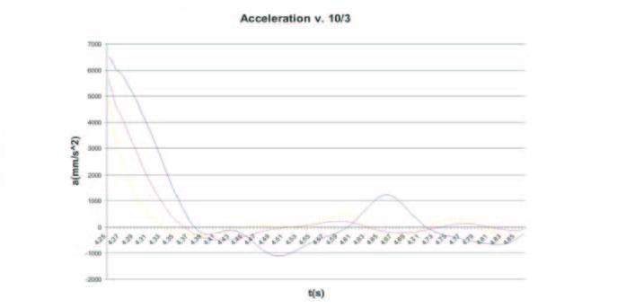
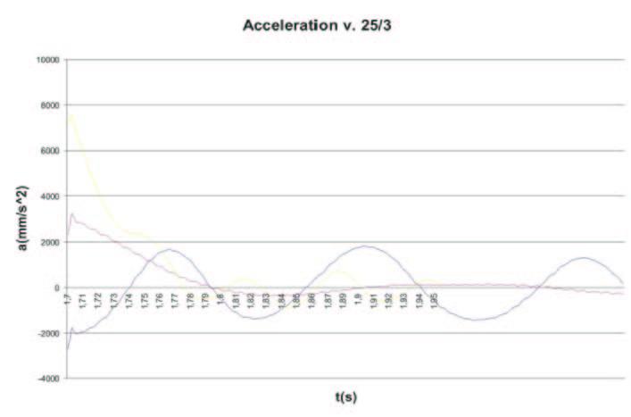
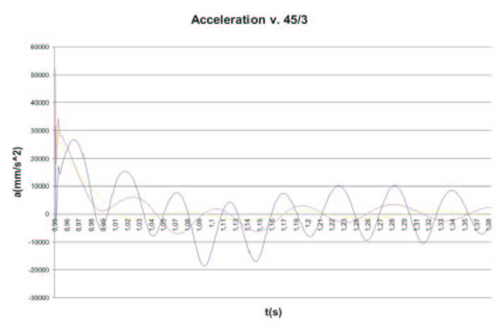
Fig. 3 – Exit from 3rd obstacle at the three examined velocity
The virtual prototypes of every single element of the suspension have been realized using the construction tables sent by specialized firms after a long period of constructive-economic briefings.
Every single element has to be connected to the other one by a precise series of mechanical bonds, created to correctly simulate its way of operating. The complex suspension assembly is constituted by 6 elements for every wheel. The lower bracket, as seen in figure 2, has its transversal dimensions imposed by the maximum distance between the spherical articulation to the chassis and the right position of the wheel bearing.
During the simulations we decided to use the same kind of Mac Pherson suspension for front and rear axle, optimising the function of this system that is able to substitute the classical transversal quadrilateral solutions with a tie rod commonly used for the rear axles.
Simulations set up
After having realized the CAD assembly of the entire light vehicle it’s possible to import the model in a VISUAL NASTRAN ambient, converting the geometrical bonds into mechanical ones.
When the model conversion is done, a phase of “exploration” is ready to be started: this option allows the observer to modify the type of bonds regarding the real way of functioning of the assembly : the quality of the results must satisfy the precision imposed to the project. VISUAL NASTRAN offers a double choose : it’s possible to use an Eulerian system of integration that leads fast and less precise results, or it’s possible to integrate the equations using the Kutta-Merson method that requires a long time evaluation waiting with accurate results.
The accuracy is checkable using three parameters: relative, absolute, acceptable errors.
1st simulation phase: damper optimisation
A vehicle is schematised like a suspended mass acting on the ground by four non-suspended masses, including the wheel and the suspension. Damping constant or elastic characteristic variations have important influence on the vehicle handling, because they modify the normal and lateral forces acting in the contact point between the wheel and the ground. The contact is simulated using a hydraulic jack system, transferring a series of sinusoidal impulses with a different mean value, with faulty timing between front and rear axle equal to the distance between the front contact point and the rear one. The equations used are:

These equations give the oscillation amplitude and tau=p/V is the time required to cover the track.
We tested the reactions of the suspension system in different asphalt surface conditions, and it has been possible to reproduce a good and a disconnected surface using a range of oscillation amplitude varying between 15mm and 60mm, typical of a paved urban surface. The virtual route does not present any curve, and so the axles aren’t forced by any kind of lateral action and the chassis is only subjected to a continuous pitching. The route length is 10m and is composed of three parts with different mean amplitude, trying to test the reaction of the suspension when this one is forced by a great vertical action, assimilable to a hump or a hole. Three different vehicles have been tested on this virtual route, each one equipped with a particular damping constant. The suspension system has a critical damping constant:

in which we used a quarter of the entire vehicle mass and a typical elastic constant K equal to 15,9 kN/m [1].
The damping effect of the tyre influences the optimal damping coefficient as follows:
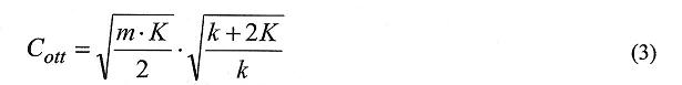
The elastic constant of the tyre k is generally 8 time bigger than the spring constant, so the second square root has a maximum value of 1,12; then it’s possible to estimate the influence of the tyre. Equation (3) counts out the silent block presence, that takes part in the roll and pitching damping and influences the vertical movement of the chassis, working in parallel with the suspension spring.
The vertical silent block is able to reduce the engine wheel toe-in variation caused by a high friction with the ground. These elements have a double action : allow the chassis suspension, blocking any kind of vertical excursion and help the damping effect. We implemented a simplified system that is able to test a great range of possible torsion resistance values in a small elaboration time. After few attempts, it’s been imposed a 1000 N m s/deg value. For every type of oscillation amplitude, three vehicles with different optimal damping coefficients have been tested in a triple speed model : 10 km/h, 25 km/h, 50 km/h.
18 simulations have been realized.
Analysis of the dynamic vehicle handling on a track
Axle characteristic
When the lateral acceleration is elevated, different types of non-linearity play an important role for the tyre reaction : lateral force is a non-linear function of the vertical load and of the drift angle.
If we want to study the iteration between the vehicle and the tyre, we have to underline the suspension deformation; the simulator has to evaluate the vertical load variations step by step, without fixing a constant value of this load during the virtual travel. The elasticity of every single suspension is comparable to an equivalent torsion rigidity acting directly upon a rotoidal bond that fixes the suspension itself to the chassis.[7]
Virtual track description
The suspension system is usually tested by the constructors by several stresses acting on the prototypes. The real car is driven through a track with some obstacles, checking the set up variations. In the same way, the virtual simulator is able to create a track that can test the vehicle dynamic reliability, giving outputs for the torsion rigidity and tyre characteristic calculation. This track, also called “Alce test”, is composed as follows:
Acceleration
Sudden steering with counter steer
New track entry
The sudden steering phase is necessary to simulate the obstacle crossing, and it’s really useful to test the damping performance of the suspension system when the car is subjected to a rotational oscillation.
The virtual track is similar to the Alce one but it’s characterized by a particular manoeuvre inspired by an urban potential use; this manoeuvre consists of a violent entry path after a hard steering, assimilable to an overtaking during the acceleration or to the hump crossing.
The obstacles disposition follows a precise idea. The first obstacle is 30m far from the start and it’s assimilable to an overtaking of a car during the acceleration. The second one is 80m far and it represents a kind of no-return point after which the vehicle must follow the right path, and at last the crossing of the third obstacle, 130m far from the start, represents the Alce test. The entire track is 200m long.
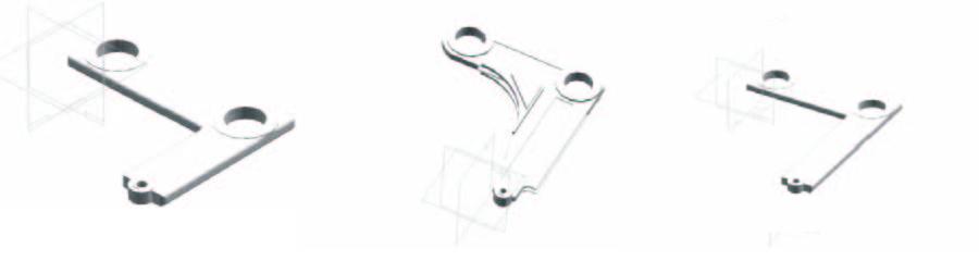
Fig. 4 – Variation of low arm geometry
Vehicle reaction to the virtual driver manoeuvres
The simulative phase allows modifications of some suspension parameters, offering the chance of testing the differences on the virtual track. It’s for this reason that we tried to optimise the geometry of the lower bracket starting from the shape of the first simulative phase. In the first attempt we tried to modify the bracket length as shown in figure 4, creating two different solutions, the first one with a 20cm bracket length and the second one with 30cm bracket, starting from the original 25cm bracket. After this step we decided to delete the second chance, because of the excessive flexing momentum augment acting upon the silent block rigid bond that cause an undesired variation of the connection joint. The length variation of the lower bracket influences the suspension ratio, defined as follows:
that is the ratio between the force acting upon the spring-damper group and the reaction force on the ground.
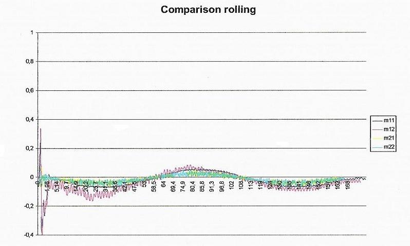
Fig. 5 – Rolling angle versus distance during the first possible manoeuvre
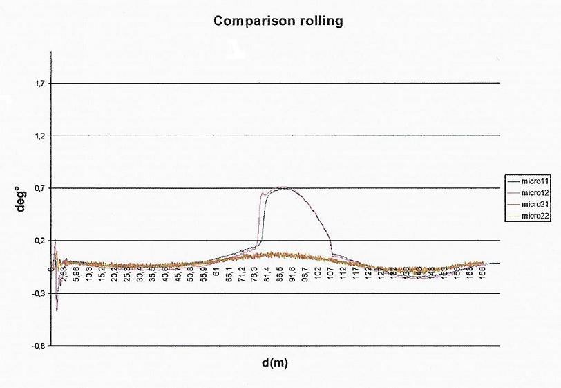
Fig. 6 – Rolling angle during the second possible manoeuvre
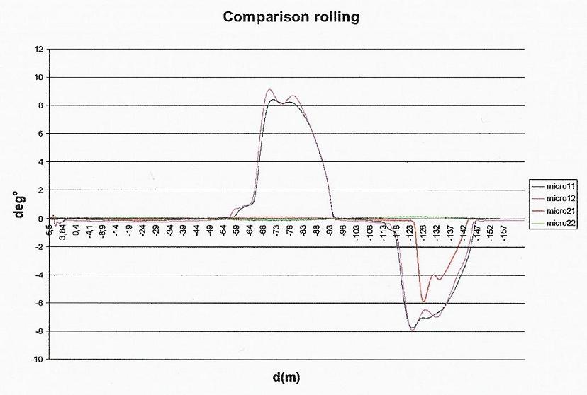
Fig. 7 – Rolling angle during the third possible manoeuvre
The shortest solution gives a higher suspension ratio than the original one, and so the simulation is also able to verify how much this quantity may influence the vehicle handling. The tested vehicles are equipped with two different geometrical configurations with different damping coefficients.
The simulation includes three possible manoeuvres of the driver:
initial acceleration covering 5m and then keeping the maximum speed allowed along the track, without modifying the path
initial acceleration covering 5m, keeping the maximum speed allowed and then a manoeuvre to correct the path
initial acceleration covering 5m, keeping the maximum speed allowed and then a fast manoeuvre to keep the control of the vehicle and overtake the following obstacles.
During the testing, also during the steering, we admit that the vehicle is guided to the maximum inlet conditions, just to verify the suspension reactions when the car is near the limit.
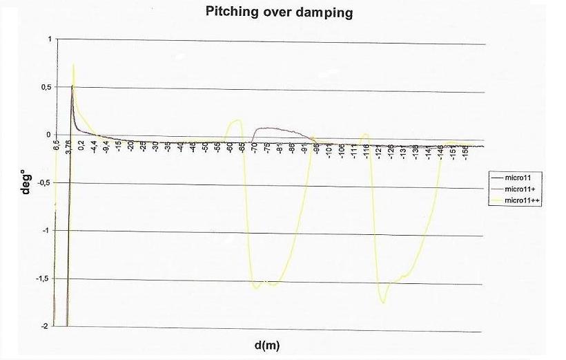
Fig. 8 – Pitching angle of over damping Light Vehicle versus distance
br>
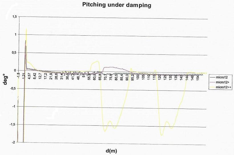
Fig. 9 – Pitching angle of under damping Light Vehicl
The simulation allows to extrapolate the paths for every kind of possible manoeuvre.
We tested four different vehicle solutions and focusing the first manoeuvre, we can admit that no vehicles are able to cover the entire track without driver’s intervention.
The original lower bracket solution seems to be more stable and less rigid than the other ones, allowing, with a loss of time, a complete recovery of the real path. Focusing the short bracket solution, we can observe that the driver has to “cut” the obstacle 100m far from the start, failing the attempt to cover the track.
Focusing the second kind of possible manoeuvre, we supposed to impose the following driver’s intervention:
first steer after 30m
a recovery of the right path between 30 and 80m
final recovery to cross the last obstacle between 80 and 130m
All the solutions tested allow the first obstacle crossing. There are some difficulties to cross the second one, because no vehicles are able to reach the second part of the track in the right position after 80m, but it’s also possible to underline that the original bracket solutions allow a better path recovery in a minor time.
The vehicles with the original bracket run out from the optimal path, but this wrong way is by-passed after the first obstacle because of the major rigidity of the short bracket solutions. Near 130m the vehicle equipped with the original bracket and under-damped suspension finishes the entire track in the right path.
The third kind of possible manoeuvre forces a great deformation of the suspension system that allows the right track covering. The solutions tested cover the entire track following the optimal path, but we have to notice that the under-dumped solution offers a better obstacle approach.
The short bracket solution loses the initial advantages: it gives good acceleration and overtaking characteristics but the vehicle handling near the end of the track is negatively influenced by a bore unsteadiness.
Roll analysis during the manoeuvres
Basing our next considerations upon recent studies, it’s better to underline that the natural oscillation of the roll angle for urban cars is about 8° [9]. Neglecting the initial variation of the roll angle caused by the first acceleration of the vehicle, it’s clear that the roll behaviour is quite similar for all solution.
When the speed is regular, the roll movement of the chassis is nearly marginal (see figure 6).
The original bracket with an under-dumped solution imposes a higher roll to the chassis than the other solutions. During the first path recovery after the curving, the suspension with the under-dumped characteristic (4000Kg/s) has a minor reaction to the roll movement of the chassis than the rigid solutions. When the virtual driver “softly” correct the vehicle path, the roll variations influence the vehicle dynamics.
When the car is near the first recovery after the obstacle, the driver’s correction causes a variation of the roll position of the chassis. If we focus the short bracket solution we can note that the hard driver’s correction during the curve recovery causes a delayed damping of the rotational oscillation.
The suspension system absorbs the reaction transmitted by the ground contact during the curve in a small period, also called “stabilization transient”. The hard steering correction modifies the vehicle set up in a period that is smaller than the stabilization transient, causing an addictive roll during the recovery phase after the obstacle. The underlined differences between the under and over dumped solutions is still present during the last test.
Pitching analysis for the original set up solution
The “wedging” inclination is related to the driver’s possible manoeuvre correction, and it’s caused by an action that is able to radically modify the transferred load between ground and tyre.
If the driver corrects the speed, the pitching variations are insignificant. But if we observe a serious manoeuvre (micro11++), the pitching variation is evident. In fact, when the driver attempts to correct the right vehicle path, there is a load transfer between the rear and font axle, that causes the front struts flattening. The last recovery manoeuvre after the third obstacle is the heaviest one for the suspension system, producing an augment of the chassis pitching inclination.
When the driver does not suddenly correct the path, there is a limited contact between wheel and ground and the strut is not stressed.
In the following picture you can see the wedging inclination of an over-dumped vehicle. The variation range of this angle is not so wide as the roll one, but the chassis tendencies are visible.
When there is an elevated wedging inclination of the chassis, near the limit allowed by the pinion-elastic gasket assembly, the silent block suddenly corrects its attitude and bring back the right chassis configuration.
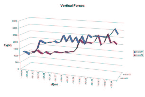
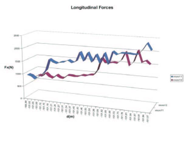
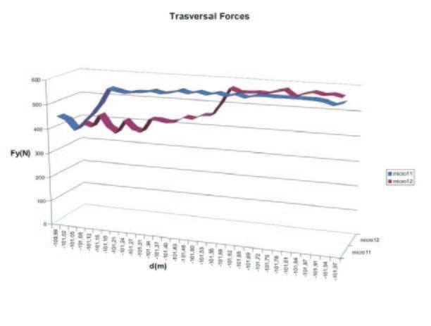
Fig. 10 – Vertical, longitudinal and transversal forces
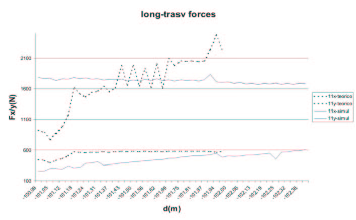

Fig. 11 – Comparison with theoretical results for both the vehicles of the test
Wheel-Ground reactions
The results previously discussed give the wheel-ground load and allow a connection between the load itself and the lateral and longitudinal forces acting upon the wheel.
Pacejka’s formula is based on some empirical values that give back the Fx and Fy components, considering a variable vertical load and a maximum oscillating camber of 1,3°.
For this test, the general empirical values for an urban vehicle have been used, equipped with 145/60/R13 tyre, with geometrical properties similar to the small vehicle in progress.
These values are : (a0..a13 = 1,3;-53,31;1190,0;588,6;2,5212;0;-0,5178;1;0;0;0;0;0;0;0;).
Figure 10-a shows the range of Fz component when the vehicle is subjected to roll variation : it’s possible to note that its maximum is about 2500N for the under-dumper vehicle and 3000N for the over-dumped solution. The under-dumped solution optimises the vertical load distribution and so the car is more reactive and has an interesting handling. Figures 10b-c show the graphs of the transversal and longitudinal forces obtained using the Pacejka’s formula.
Figure 11 shows that the transversal component value is similar to the simulative one, while the longitudinal one is different from the expected one. After a transient period during which the tyre tries to adapt its behaviour to the ground, the contact tyre-ground varies around the expected line. It’s possible to conclude that we confirmed the analytical hypothesis; and so it’s also possible to establish the simulation validity.
Torsion rigidity analysis
The suspension strut allows a maximum excursion of 85 mm. We suppose to develop 95% of this value to possible correction of the dynamic stability during a braking, a curve or during acceleration.
When the vehicle reaches the track point in which the driver hardly corrects the path, it’s subjected to the following lateral acceleration:
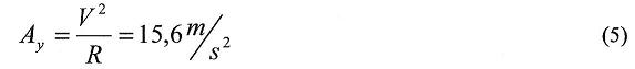
Using previously studies [10] it’s possible to evaluate the torsion rigidity, the load transfer from the inside wheel to the outside one and, at last, the vertical suspension excursion constant that is:

The oscillation frequency is:
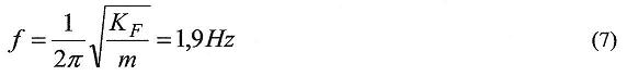
where m is the non-suspended front mass (18 Kg).
The ride oscillation frequency [10] defines the front or rear axle oscillation during the movement of the vehicle. The obtained value is coherent to the fixed comfort necessities.
It’s possible to admit that a frequency reduction, that could be necessary to make the front axle softer, is possible using a different distribution of the total torsion rigidity, or modifying the front silent blocks.
Analytical calculations, based on the exact value of the torsion rigidity, give back a 2273,64N left-wheel transferred vertical load.
The first set of simulations underlined a better damping performance of the under-dumped solution; the second set underlines the better handling of the same kind of vehicle.
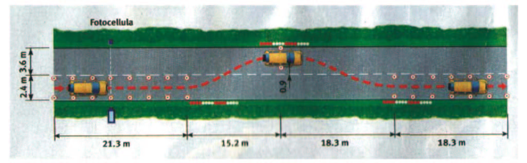
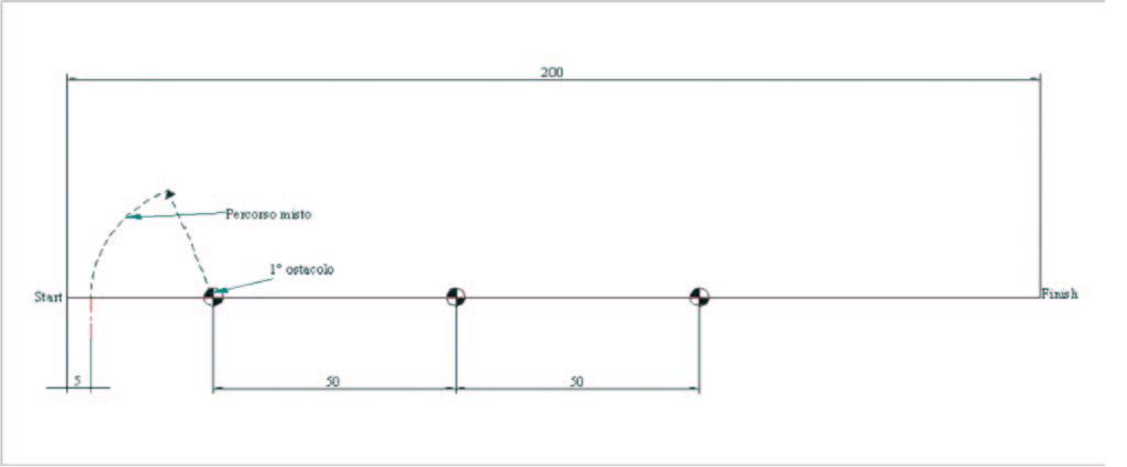
Fig. 12 – Alce test (top) and simulation route (bottom)
CONCLUSIONS
We based our studies on the results given by GUERRERA firm, using VISUAL NASTRAN 4D software. These inputs had fixed the essential data for the choice of a base suspension system.
The mechanical frame simulation around the driver consists of the application of an analytical-simulative method which is able to adapt the fundamental suspension characteristics, like for example the damping coefficient and torsion rigidity, to the maximum dynamic stability in any condition, without comfort losses. We tried to optimise the stability without neglecting the comfort because we have to think about the physical condition of the future driver which is maybe afflicted by natural problems and is interested in a kind of mechanical extension of his legs.
We started the work analysing the optimal geometric set up of the suspension, using innovative parameters like CRC (combined roll centre), and then the optimal set up data have been imported into the simulation code, that allowed to develop the last two phases of our work: optimal damping coefficient and virtual track testing of the vehicle equipped with the optimal solution. The absence of past data complicated things; in spite of all this, our results confirmed the rare data known about the optimal parameters of small car suspensions.
The focus of the first phase has been to find an iteration between oscillatory, vibratory and geometric parameter. Testing the car on a virtual track, it has been possible to study the influence of these parameters on the suspension behaviour. We compared the ratio C/Cott to the results of some testes on a small car, extrapolating this value from the literature data. For a small car this ratio is about 1.53, and is about 1.6 for the under-dumped vehicle. ottC
The focus of the second phase has been to find a relation between comfort and dynamic stability. Creating a virtual track, it’s been possible to test the suspension reaction after different manoeuvres. We tested the vehicles equipped with under ad over dumped suspensions and with geometrical variations of the lower bracket. We signed the under-dumped solution as the best possible because it’s able to absorb the reactions transmitted by the wheel-ground contact and offers a good stability during the track covering.
It’s been possible to compare the load transmitted in the wheel-ground contact, comparing these results with those one obtained by an analytical method, and signing a good consistency; we estimated a frequency value of the front axle comparable to the one read in literature data.
BIBLIOGRAPHY
[1] Giancarlo Genta - MECCANICA DELL’AUTOVEICOLO - Levrotto & Bella, Torino, 1992
[2] Jeffrey Daniels - CAR SUSPENSIONS AT WORK - Motor Racing Publications LTD
[3] Chris Rees - SPECIALIST CARS - Windrow & Green
[4] Nelson Barbieri - SUSPENSIONS OPTIMIZATION – SAE Technical Papers, Mobility technology conference & exhibit, Sao Paulo, Brasil, October 13-14, 1992
[5] Zagatti, Zennaro, Pasqualetto - L’ASSETTO DELL’AUTOVEICOLO - Levrotto & Bella, Torino
[6] John Fenton - HANDBOOK OF AUTOMOTIVE POWERTRAIN AND CHASSIS DESIGN - Professional Engineering Publishing Limited
[7] Massimo Guiggiani - DINAMICA DEL VEICOLO - Cittŕ studi Edizioni
[8] J. R. Ellis - VEHICLE HANDLING DYNAMICS - MEP London
[9] M. B. Gerrard - ROLL CENTRES JACKING FORCES INDIPENDENT SUSPENSIONS. A FIRST PRINCIPLE EXPLAINATION AND A DESIGNER’S TOOLKIT - SAE Technical Papers, International congress and exposition, Detroit, Michigan, March 1-4, 1999
[10] William F. Milliken, Douglas L. Milliken - RACE CAR VEHICLE DYNAMICS - SAE International
[11] Virzě Mariotti G., Duboka C.: Definition of the Suspension Ratio and Its Use with Application to a Squaring Suspension, Automotive Technology for Better Quality of Life, JUMV Special Publication JUMV-SP-9901, Belgrade, Yugoslavia, 1999, p. 5
[12] Virzě Mariotti G. – Some Observations on the Best Damping Constant - XVIII Science and Motor Vehicles 2001 – Belgrade, 28-30 May 2001
OTHER 83 DIFFERENT APPLICATIONS !
ALTRI 83 CASI IN SETTORI DIVERSI !