This section follows the steps for design optimization to design a rocker arm part.
Step 1: Define the design space and boundary conditions
- Figure 1 shows the design space defined in the CAD system for a rocker
arm part. The part is restrained with pinned restraints through the horizontal
hole and a simulated point restraint near the left end. The right end is
loaded parallel to the vertical hole with a total face load of 40 lbs.
The part will be manufactured with the Steel - ANSI 304 material.
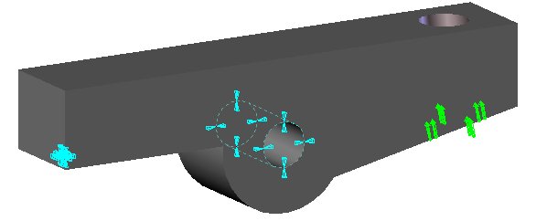
Figure 1: Design space and boundary conditions.
|
|
|||||
| Step 1 | Step 2 | Step 3 | Step 4 | Step 5 | Step 6 |